Replaceable forming mold and soldering tin sleeve forming equipment and method

A technology for forming molds and forming equipment, which is applied in the field of production equipment and process improvement of heat-shrinkable sleeves, can solve the problems of inability to meet production requirements, inability to automate batch production, and low processing efficiency, so as to achieve convenient repair and maintenance, and convenient Mounting and dismounting, the effect of improving processing efficiency

Active Publication Date: 2018-12-18
SHANGHAI CHANGYUAN ELECTRONICS MATERIAL
View PDF9 Cites 0 Cited by
  • Summary
  • Abstract
  • Description
  • Claims
  • Application Information

AI Technical Summary

Problems solved by technology

In the prior art, solder sleeves are generally formed by manual production on the basis of basic heat shrinkable sleeves. The processing efficiency is low, and it cannot be automated and mass-produced, and cannot meet production requirements.

Method used


Image

  • Replaceable forming mold and soldering tin sleeve forming equipment and method
  • Replaceable forming mold and soldering tin sleeve forming equipment and method
  • Replaceable forming mold and soldering tin sleeve forming equipment and method

Examples


specific Embodiment 1

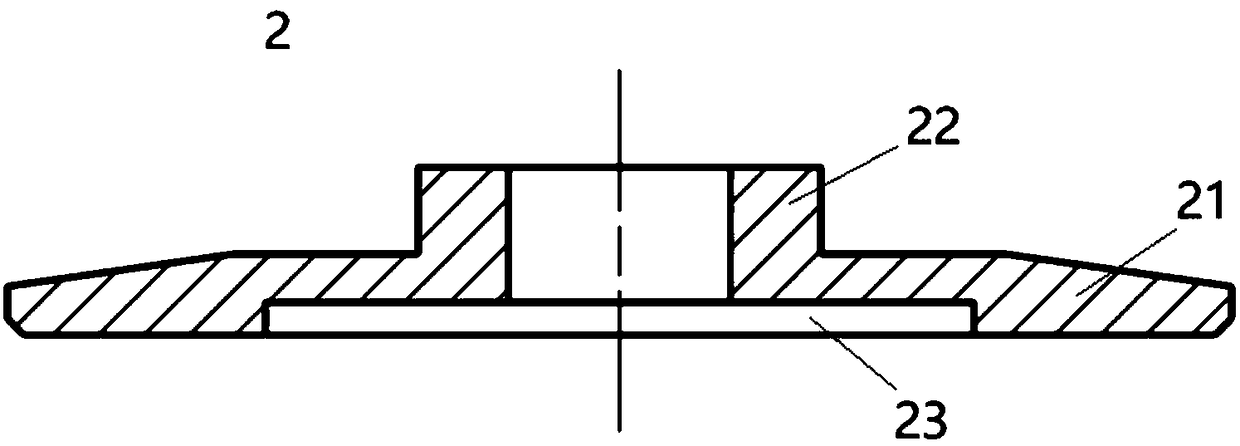
[0035] Such as Figure 1~3 As shown, this specific embodiment discloses a replaceable molding die, including: a stepped shaft 1, a gasket 2 and a fixing member 3, wherein the stepped shaft 1 includes a collar step 11, a gasket step 12, The snap ring step 13 and the locking step 14, the collar step 11 includes the first step 111, the second step 112 and the third step 113 whose outer diameter increases sequentially, the third step 113 is connected with the gasket step 12, and the gasket step 12 The outer diameter of the collar step 11 is greater than the outer diameter of the third step 113, and the outer diameter of the snap ring step 13 is greater than the outer diameter of the gasket step 12 and the locking step 14. Wherein, the first step 111 , the second step 112 and the third step 113 are respectively used for installing the first rubber ring, the tin ring and the second rubber ring.

[0036] In this embodiment, the gasket 2 is detachably sleeved on the gasket step 12 an...

specific Embodiment 2

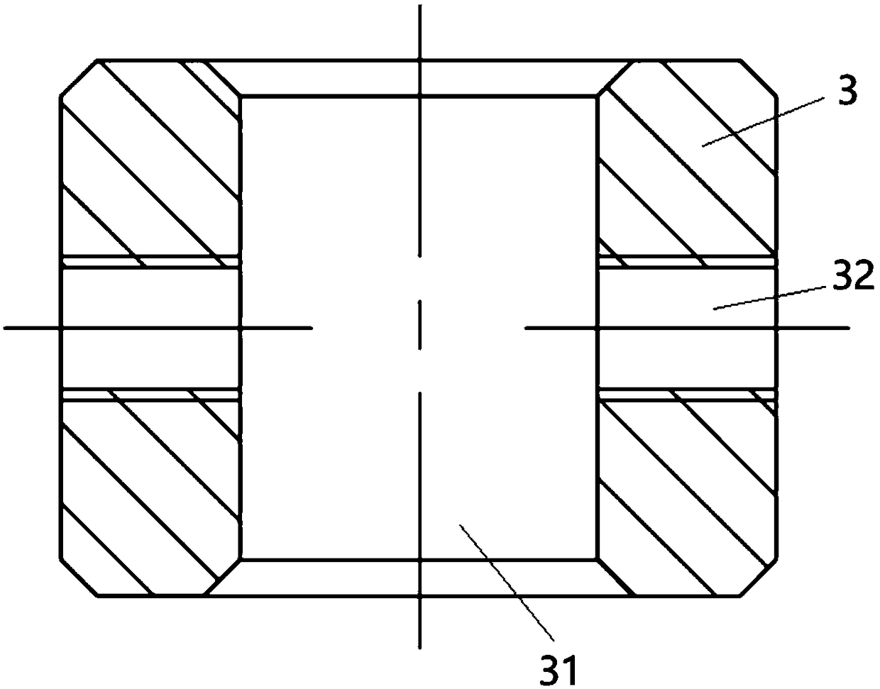
[0040] This specific embodiment discloses a solder sleeve molding equipment, including: the replaceable molding die disclosed in the first specific embodiment, an operating platform and a heating device, the operating platform has a mounting hole, and the diameter of the mounting hole is larger than or It is equal to the outer diameter of the locking step in the stepped shaft, and the diameter of the installation hole is smaller than the outer diameter of the snap ring step in the stepped shaft. In this way, after the locking step of the stepped shaft passes through the operating platform, the snap ring step can be stuck on the operating platform On the upper surface of the upper surface, then fix the fixing part on the locking step, so that the fixing part is stuck on the lower surface of the operating platform, and the axial positioning of the stepped shaft can be completed through the cooperation of the snap ring step, the fixing part and the operating platform. After the st...

specific Embodiment 3

[0045] This specific embodiment discloses a method for forming a solder sleeve. The method specifically adopts the solder sleeve forming equipment in Embodiment 2. The automatic ring adding method includes the steps:

[0046] S10: Thread the locking step in the stepped shaft into the installation hole of the operating platform, and the snap ring step in the stepped shaft is stuck on the upper surface of the operating platform;

[0047] S20: Fix the fixing part on the locking step in the ladder shaft, and the fixing part is stuck on the lower surface of the operation platform;

[0048] S30: set the gasket on the gasket step;

[0049] S40: Sleeve the first rubber ring, the tin ring, and the second rubber ring on the first step, the second step, and the third step of the collar steps in sequence;

[0050] S50: Put the heat-shrinkable sleeve on the gasket after passing through the step of the collar;

[0051] S60: Heat the heat-shrinkable sleeve located at the collar through the...


PUM


Abstract

The invention discloses a replaceable forming mold and soldering tin sleeve forming equipment and method. The replaceable forming mold comprises a stepped shaft, a gasket and a fixing member. The stepped shaft comprises a lantern ring step, a gasket step, a snap ring step and a locking step which are connected in sequence. The outer diameter of the gasket step is larger than the outer diameter ofthe lantern ring step, and the outer diameter of the snap ring step is larger than the outer diameters of the gasket step and the locking step. The gasket is detachably arranged on the gasket step ina sleeving mode and matched with the snap ring step, and the gasket is used for fixing a heat-shrinkable sleeve. The fixing member is detachably connected to the locking step, and a mounting space forbeing matched with an operation platform is arranged between the fixing member and the snap ring step. The replaceable forming mold is simple in structure and low in cost, and can be used for automatic production of soldering tin sleeves; automatic ring-adding device is simple in composition and convenient to operate, can realize automatic and batch production of the soldering tin sleeves, and isconvenient to repair and maintain; and an automatic ring-adding method has fewer steps and is easy to operate and high in processing efficiency.

Description

technical field [0001] The invention relates to the technical field of manufacturing equipment and process improvement of heat-shrinkable sleeves, in particular to a replaceable forming mold and solder sleeve forming equipment and method. Background technique [0002] With the continuous development and innovation of the heat shrinkable tube application field, a new heat shrinkable product has appeared on the market: solder sleeve, compared with the existing heat shrinkable tube, the solder sleeve has a special structure, and the solder sleeve The end is provided with a plurality of collars in turn, generally including two rubber rings and a tin ring, along the axial direction of the casing, the rubber ring and the tin ring are arranged coaxially, and the tin ring is generally located in the middle of a pair of rubber rings. In the prior art, solder sleeves are generally formed by manual production on the basis of basic heat-shrinkable sleeves. The processing efficiency is l...

Claims


Application Information

Patent Timeline
Patent Type & Authority Applications(China)
IPC IPC(8): B29C61/02B29C33/30
CPCB29C33/306B29C61/025
Inventor 李俊杰顾陆於聂云
Owner SHANGHAI CHANGYUAN ELECTRONICS MATERIAL
Why Eureka
Try Eureka