An energy-absorbing connecting structure and an automobile seat connecting structure

A technology that can connect and connect holes, applied in vehicle seats, vehicle parts, transportation and packaging, etc., can solve the problems of no impact force buffering effect, poor connection reliability, etc., to achieve high connection reliability and buffer impact force.

Pending Publication Date: 2018-12-18
GAC COMPONENT CO LTD
View PDF0 Cites 0 Cited by
  • Summary
  • Abstract
  • Description
  • Claims
  • Application Information

AI Technical Summary

Problems solved by technology

[0005] The technical problem to be solved by the present invention is to provide an energy-absorbing connection structure and a car seat connection structure to solve the problems that the existing connection structure has no buffering effect on the impact force and poor connection reliability

Method used


Image

  • An energy-absorbing connecting structure and an automobile seat connecting structure
  • An energy-absorbing connecting structure and an automobile seat connecting structure
  • An energy-absorbing connecting structure and an automobile seat connecting structure

Examples


Embodiment 1

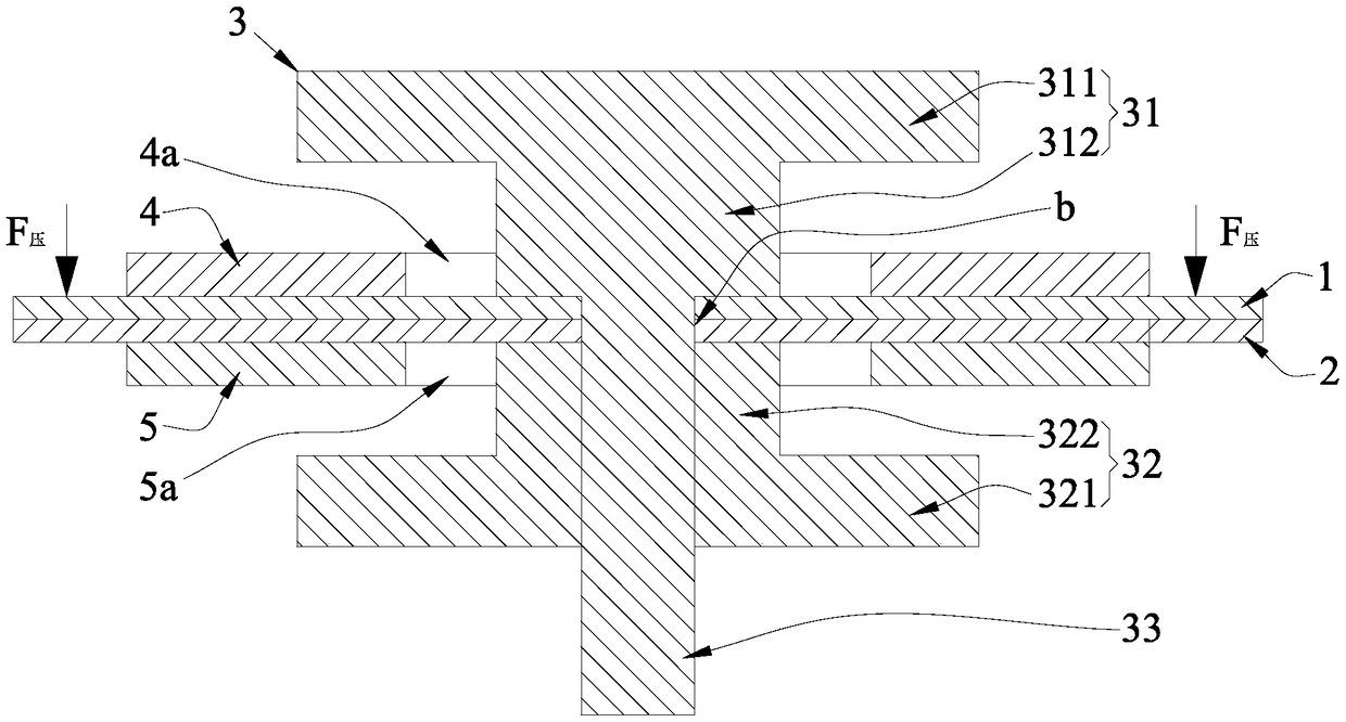
[0046] Such as Figure 1 to Figure 3 As shown, this embodiment one discloses an energy-absorbing connection structure for connecting the first plate 1 and the second plate 2; the energy-absorbing connection structure is provided with a connecting piece 3, which has a first The end head 31 , the second end head 32 and the rod portion 33 connected between the first end head 31 and the second end head 32 .

[0047] The first plate material 1 and the second plate material 2 are respectively provided with a first through hole 1a and a second through hole 2a, and the first plate material 1 and the second plate material 2 are attached so that the first through hole 1a and the second through hole 2a The two through holes 2a communicate to form a connection hole b, and the rod portion 33 of the connector 3 passes through the connection hole b, so that the first plate 1 and the second plate 2 are clamped on the first plate of the connector 3 . Between the end 31 and the second end 32 ....

Embodiment 2

[0061] On the basis of the first embodiment above, the second embodiment also adopts the following preferred structure:

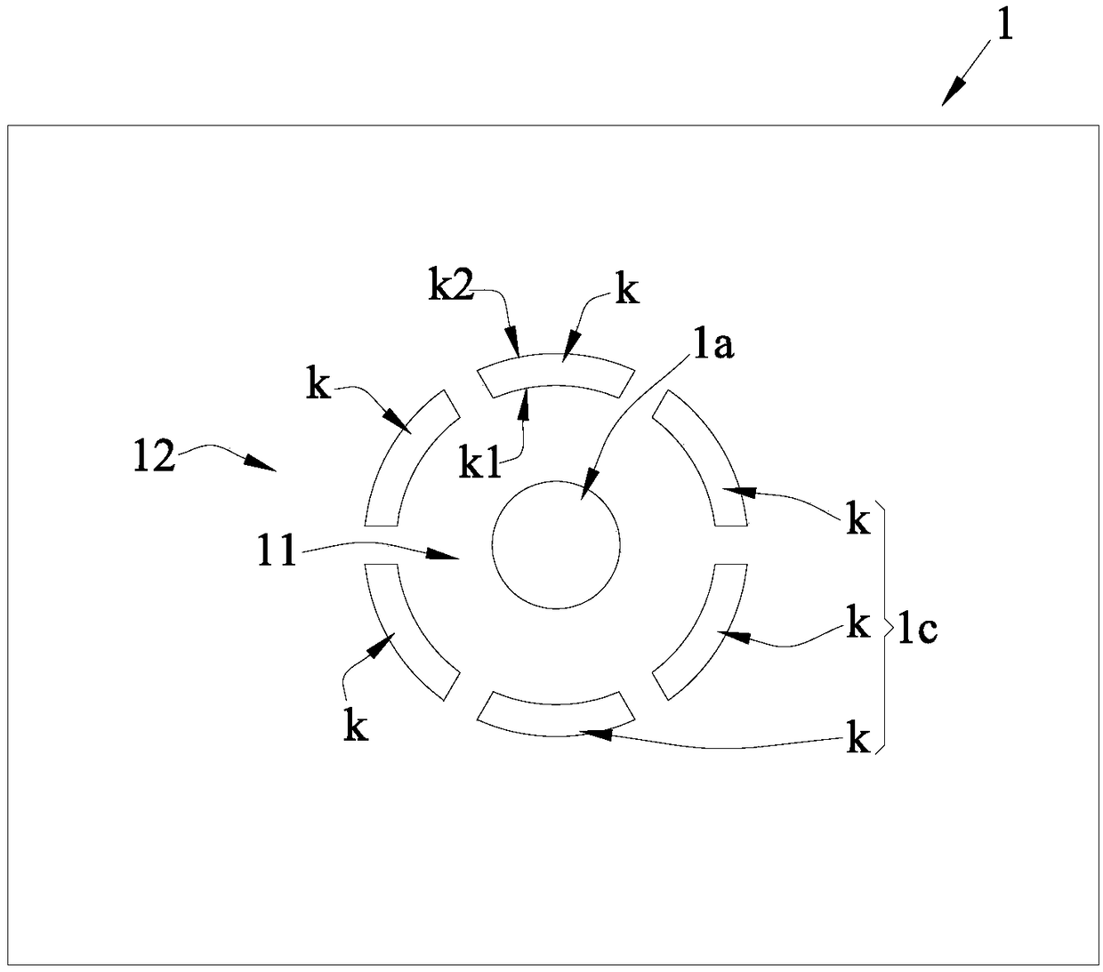
[0062] The first rigidity weakening structure 1c is an intermittent annular groove structure;

[0063] Wherein, the intermittent annular groove structure includes a plurality of slots k, and each of the slots k is evenly spaced around the through holes on the plate where the slots k are used to form the connecting holes b;

[0064] Such as figure 2 As shown, for the second embodiment, that is, the slots k of the first weakening structure 1 c are evenly spaced around the first through hole 1 a of the first board 1 .

Embodiment 3

[0066] On the basis of the first embodiment above, the third embodiment also adopts the following preferred structure:

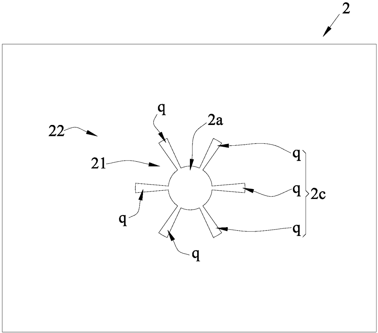
[0067] The first rigidity weakening structure 1c is a star-shaped notch structure;

[0068] Wherein, the star-shaped notch structure includes a plurality of notches q, and each notch q communicates with a through hole on the plate where it is located for forming the connecting hole b and extends along the radial direction of the through hole, and each of the notches q The notches q are evenly spaced around the through-holes on the plate where they are used to form the connection holes b (the arrangement of the notches q relative to the through-holes can be found in image 3 ).

[0069] For the third embodiment, that is: each of the notches q of the first weakening structure 1c communicates with the first through hole 1a of the first plate 1 and extends along the radial direction of the first through hole 1a, and each The notches q are evenly spaced around ...


PUM

PropertyMeasurementUnit
Thicknessaaaaaaaaaa

Abstract

The invention discloses an energy-absorbing connecting structure and an automobile seat connecting structure, A first rigidity weaken structure is provided on the first plate, using the first end of the step structure, and providing a first reinforcing plate, when the first plate is subjected to a pressure or a tensile force of a normal magnitude, can normally transmit the force to the second plate, when the first plate is subjected to a sudden increase in tensile force, utilizing the characteristic that the connection strength between the first hole edge region and the first peripheral regionon the first plate is weakened by the first rigid weakening structure, the shock energy generated by the tensile force is absorbed by the large deformation of the first plate and the shear fracture,so as to cushion the relative movement between the first plate and the second plate, and the use of the first reinforcing plate ensures that the force can be transmitted between the first plate and the second plate even in the case where the first hole edge region of the first plate is cut. The invention has the advantages of buffering impact force and high reliability of connection.

Description

technical field [0001] The invention relates to an energy-absorbing connection structure and an automobile seat connection structure using the energy-absorbing connection structure. Background technique [0002] Bolts, riveting and other connection structures, due to their connection characteristics, when the structure is under tension, the dispersed and uniform force of the parts will be concentrated on the bolts, and the force will continue to be transmitted to the next part through the bolts. Therefore, in the bolt connection The hole will be subjected to a very large concentrated force, and the plate is prone to large deformation at the connection hole. [0003] Many connecting structures of automobiles are subjected to very small loads during normal use, such as the connecting structure of the seat. When the occupant is riding normally, the concentrated force on the connecting parts is very small, which is far less than the strength limit of the connecting parts. When ...

Claims


Application Information

Patent Timeline
IPC IPC(8): B60N2/42
CPCB60N2/4249B60N2/4228
Inventor 黄政平张国杰朱新涛杨公可王春红
Owner GAC COMPONENT CO LTD
Why Eureka
Try Eureka