Eureka AIR delivers breakthrough ideas for toughest innovation challenges, trusted by R&D personnel around the world.

Hydrogen supply device for chemical hydrogen production and nanometer hydrogen dissolution water machine using chemical hydrogen production as hydrogen source

A hydrogen-dissolving water machine and chemical technology, applied in the field of nano-hydrogen-dissolving water machines, can solve the problems of high cost, waste, and low hydrogen production by the hydrogen-dissolving machine, and achieve the effect of saving costs and avoiding waste.

Pending Publication Date: 2018-12-18
安徽合巢氢产业应用技术研究院有限公司
View PDF7 Cites 2 Cited by
  • Summary
  • Abstract
  • Description
  • Claims
  • Application Information

AI Technical Summary

Problems solved by technology

[0006] The technical problem to be solved by the present invention is that the hydrogen production capacity of the existing hydrogen dissolving machine is small, which cannot meet the requirement of adjusting the human body's biological balance skills, and the cost is relatively high, while the general chemical hydrogen production continuously produces hydrogen, resulting in waste

Method used


Image

  • Hydrogen supply device for chemical hydrogen production and nanometer hydrogen dissolution water machine using chemical hydrogen production as hydrogen source
  • Hydrogen supply device for chemical hydrogen production and nanometer hydrogen dissolution water machine using chemical hydrogen production as hydrogen source
  • Hydrogen supply device for chemical hydrogen production and nanometer hydrogen dissolution water machine using chemical hydrogen production as hydrogen source

Examples


Embodiment Construction

[0028] In order to facilitate those skilled in the art to understand the technical solution of the present invention, the technical solution of the present invention will now be further described with reference to the accompanying drawings.

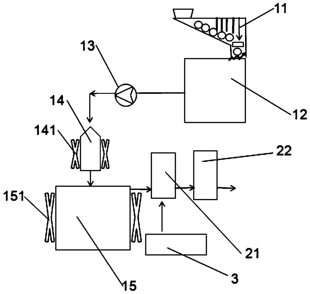
[0029] figure 1 Shown is a schematic structural diagram of the hydrogen supply device for chemical hydrogen production disclosed in this embodiment, which includes a hydrogen generating mechanism, a conveying mechanism and a cooling unit 3 . The hydrogen generating mechanism is used for producing hydrogen by reaction, the conveying mechanism is used for transporting the produced hydrogen to the hydrogen dissolving device, and the cooling unit 3 is used for cooling the device.

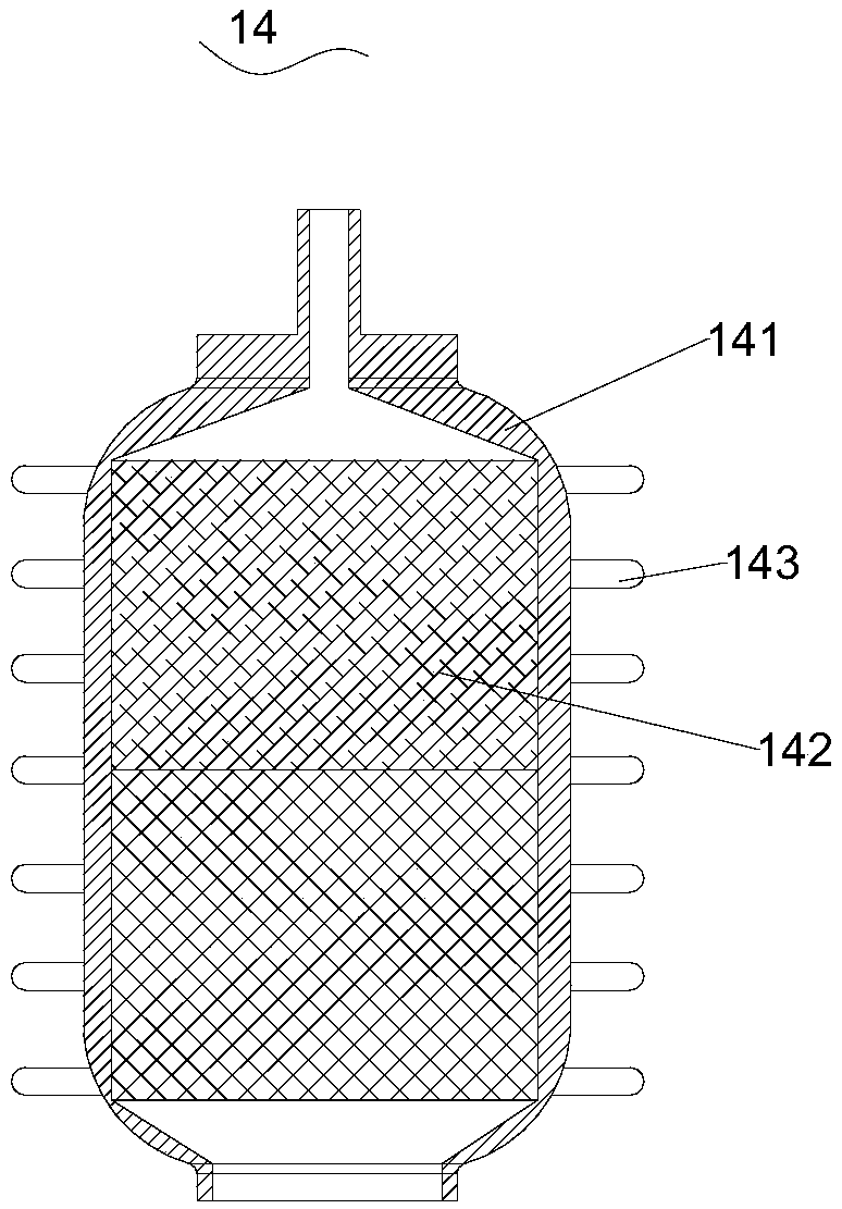
[0030] The hydrogen generating mechanism includes a medicament box 11 , a solution tank 12 , a peristaltic pump 13 , a reactor 14 and a waste liquid tank 15 which are connected in sequence.

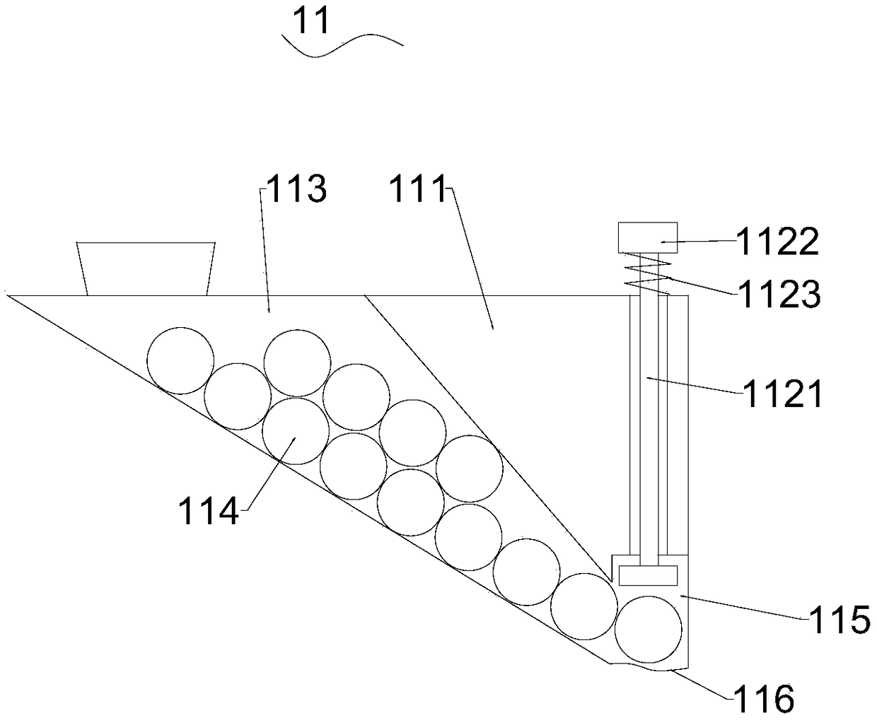
[0031] see figure 2 , the medicine box 11 includes a box body 111 and ...


PUM


Abstract

The invention discloses a hydrogen supply device for chemical hydrogen production. The device comprises a hydrogen generation mechanism and a delivery mechanism, wherein the hydrogen generation mechanism comprises an agent box, a solution box, a peristaltic pump, a reactor and a waste liquid box which are connected in sequence; the agent box comprises a box body and an adjustment switch, an oblique agent storage cavity is formed in the box body, agent particles are stored in the agent storage cavity, a vertical agent blanking area is connected with the lower end of the agent storage cavity, ablocking cover is arranged at the lower end of the agent blanking area, and when the blocking board is under stress, a channel for the agent particles to pass through is formed; the adjustment switchcomprises an extrusion rod, the diameter of the lower end of the extrusion rod is equal to that of the agent blanking area, the lower end of the extrusion rod slides in the agent blanking area vertically, and the upper end of the extrusion rod extends to the outer portion of the box body straight up; an air outlet is formed in the waste liquid box; one end of the delivery mechanism is connected with the air outlet. The invention further discloses a hydrogen dissolution water machine using the hydrogen supply device for chemical hydrogen production. The hydrogen supply device for chemical hydrogen production and the hydrogen dissolution water machine using the hydrogen supply device for chemical hydrogen production have the advantages that the hydrogen production amount is large, the priceis cheap, and the hydrogen content of obtained hydrogen dissolution water is high.

Description

technical field [0001] The invention belongs to the technical field of drinking water equipment, and particularly relates to a hydrogen supply device for chemical hydrogen production and a nano-hydrogen dissolving water machine using chemical hydrogen production as a hydrogen source. Background technique [0002] Dissolved hydrogen water, also known as hydrogen-rich water, as the name suggests, is a hydrogen-rich water formed by dissolving a part of hydrogen in the water. [0003] As early as July 2007, Professor Ohta of Japan Medical University published a paper in "Natural Medicine" saying that breathing 2% hydrogen in animals can effectively scavenge free radicals and significantly improve cerebral ischemia-reperfusion injury. As a selective antioxidant substance, hydrogen has a therapeutic effect on various diseases and has a very broad application prospect. It completely overturns the traditional view that hydrogen is a physiologically inert gas, and suggests that hydro...

Claims


Application Information

Patent Timeline
Patent Type & Authority Applications(China)
IPC IPC(8): C01B3/06C02F1/68
CPCC01B3/065C02F1/68C02F2209/30B01J2219/00018Y02E60/36
Inventor 孙元明
Owner 安徽合巢氢产业应用技术研究院有限公司
Why Eureka
Eureka Blog
Learn More