Differential locking mechanism

一种锁止机构、差速锁的技术,应用在差速传动装置、机械设备、传动装置等方向,能够解决技术和材料要求高、锁止过程复杂、反应速度慢等问题,达到技术和材料要求低、结构简单、反应灵敏的效果

Inactive Publication Date: 2018-12-18
郭放
View PDF5 Cites 11 Cited by
  • Summary
  • Abstract
  • Description
  • Claims
  • Application Information

AI Technical Summary

Problems solved by technology

[0002] At present, some of the existing differential locking mechanisms have complex structures, some require high technology and materials, are not easy to manufacture and are expensive, some have complicated locking processes, require parking or low speed to lock, and some have slow response speeds. Some structures have low strength and are not durable

Method used


Image

  • Differential locking mechanism
  • Differential locking mechanism
  • Differential locking mechanism

Examples


Embodiment 1

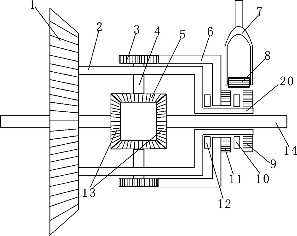
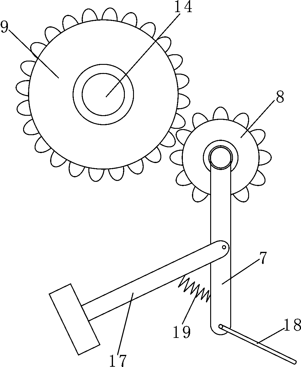
[0009] Now refer to the attached figure 1 And attached image 3 , described in conjunction with the embodiment as follows: a differential locking mechanism, including a differential and a locking mechanism, the differential includes a driven gear 1, a differential housing 2, a half shaft 14, a bevel gear, One end of the differential case 2 is fixedly provided with a driven gear 1, and two ends of the differential case 2 are respectively provided with a semi-shaft 14 for rotation, and the two semi-shafts 14 face the outside of the differential case 2 One end is rotatably connected with an axle housing, and one end of the two half shafts 14 facing the differential case 2 is respectively fixed with a bevel gear A13, and one side of the differential case 2 is rotatably arranged on the case wall. There is a rotating shaft 4, and a bevel gear B5 is fixedly arranged at one end of the rotating shaft 4 towards the inside of the differential case 2, and the bevel gear B5 meshes with tw...

Embodiment 2

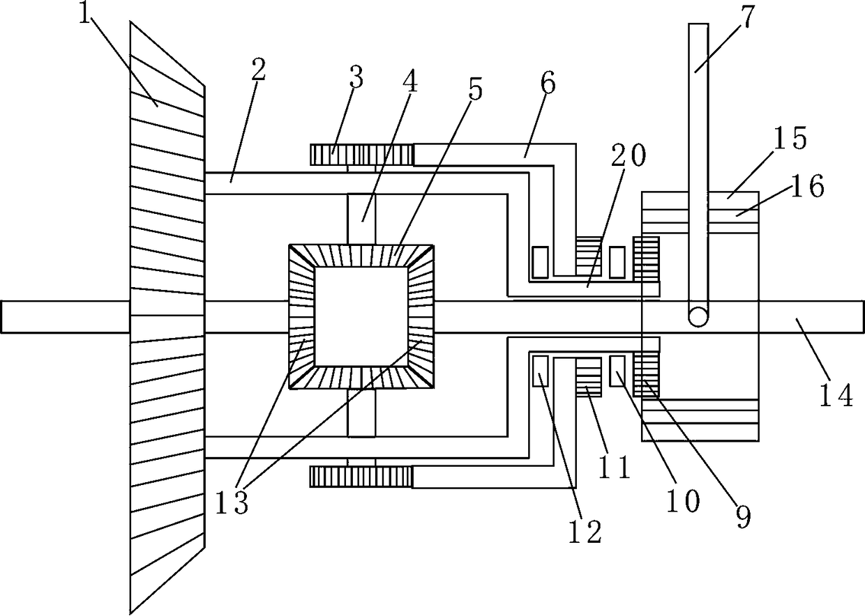
[0014] Now refer to the attached figure 2 , described in conjunction with the embodiment as follows: a differential locking mechanism, including a differential and a locking mechanism, the differential includes a driven gear 1, a differential housing 2, a half shaft 14, a bevel gear, One end of the differential case 2 is fixedly provided with a driven gear 1, and two ends of the differential case 2 are respectively provided with a semi-shaft 14 for rotation, and the two semi-shafts 14 face the outside of the differential case 2 One end is rotatably connected with an axle housing, and one end of the two half shafts 14 facing the differential case 2 is respectively fixed with a bevel gear A13, and one side of the differential case 2 is rotatably arranged on the case wall. There is a rotating shaft 4, and a bevel gear B5 is fixedly arranged at one end of the rotating shaft 4 towards the inside of the differential case 2, and the bevel gear B5 meshes with two bevel gears A13. Wh...


PUM


Abstract

The invention provides a differential locking mechanism. The differential locking mechanism comprises a differential mechanism and a locking mechanism. A gear A is fixedly arranged at the end, towardsthe outside of a differential mechanism shell, of a rotary shaft, a sleeve is integrally arranged at the right end of the differential mechanism shell, a semi-shaft located on the right side of the differential mechanism shell is sleeved with the sleeve, and the sleeve and the semi-shaft are movably connected. A gear B is fixedly arranged on the sleeve, the right end of the differential mechanismshell is sleeved with a barrel-shaped gear, the barrel-shaped gear and the differential mechanism shell are rotationally connected, the barrel-shaped gear and the sleeve are rotationally connected, insection is fixedly arranged at the position of an opening of the barrel-shaped gear, the barrel-shaped gear and the gear A are engaged, a gear C is fixedly arranged at the tail end of the barrel-shaped gear, the sleeve is sleeved with the gear C, and the gear C and the sleeve are rotationally connected.

Description

technical field [0001] The invention relates to the field of auto parts, in particular to a differential locking mechanism. Background technique [0002] At present, some of the existing differential locking mechanisms have complex structures, some require high technology and materials, are not easy to manufacture and are expensive, some have complicated locking processes, require parking or low speed to lock, and some have slow response speeds. Some structures have low strength and are not durable. Contents of the invention [0003] The purpose of the present invention is to overcome the shortcomings of the prior art and provide a differential locking mechanism with a relatively simple structure and durability. It has low requirements on technology and materials, and is easy to manufacture and assemble. The locking operation is simple and responsive, and it can be locked without stopping or reducing the speed of the vehicle. It can be started manually, and can also be ...

Claims


Application Information

Patent Timeline
Patent Type & Authority Applications(China)
IPC IPC(8): F16H48/12F16H48/24
CPCF16H48/12F16H48/24F16H48/08F16H48/22F16H2048/366
Inventor 郭放
Owner 郭放
Why Eureka
Try Eureka