Magnetic levitation 3D printed moon lamp

A 3D printing and magnetic levitation technology, which is applied in the field of moon lamps, can solve the problems of low changeability, inability to rotate light, low interest and viewing, and achieve high viewing, good visual enjoyment, and strong interest.

Pending Publication Date: 2018-12-18
揭阳安麦思科技有限公司
0 Cites 0 Cited by

AI-Extracted Technical Summary

Problems solved by technology

At present, the luminous spheres of 3D printed moon lamps on the market are mostly fixed structures, which cannot rotate and emit light like the moon...

Abstract

The invention belongs to the technical field of moon lamps, and particularly relates to a magnetic levitation 3D printed moon lamp. The magnetic levitation 3D printed moon lamp comprises a 3D printedsphere, an acrylic cover, a 3D printed magnetic tray, a permanent magnet set tray, a receiving coil, a receiving coil fixing cover, an LED luminous chipset, a magnetic levitation base chipset, a magnetic levitation base power adapter and a limiting magnet set base. The 3D printed sphere is of a hollow structure and an opening is formed in the lower end. The acrylic cover is used for protecting the3D printed sphere. The 3D printed magnetic tray and the 3D printed sphere are connected to be combined into a sphere, and a limiting ring is connected to the middle portion of the inner side of the 3D printed magnetic tray. The permanent magnet set tray is arranged on the inner side of the limiting ring. The receiving coil is located on the lower side of the permanent magnet set tray. The receiving coil fixing cover is used for fixing the receiving coil. The LED luminous chipset is located on the upper side of the receiving coil fixing cover and is electrically connected with the receiving coil. The magnetic levitation base chipset is used for enabling the 3D printed sphere to suspend, rotate and glow. The magnetic levitation base power adapter is used for supplying power to electronic components. The limiting magnet set base is located on the lower side of the magnetic levitation base chipset. The magnetic levitation 3D printed moon lamp has the advantage that after the magnetic levitation 3D printed moon lamp is electrified, the spherical surface can stably glow while suspending and rotating.

Application Domain

Lighting support devicesPoint-like light source +4

Technology Topic

ChipsetEngineering +3

Image

  • Magnetic levitation 3D printed moon lamp
  • Magnetic levitation 3D printed moon lamp
  • Magnetic levitation 3D printed moon lamp

Examples

  • Experimental program(1)

Example Embodiment

[0027] Example
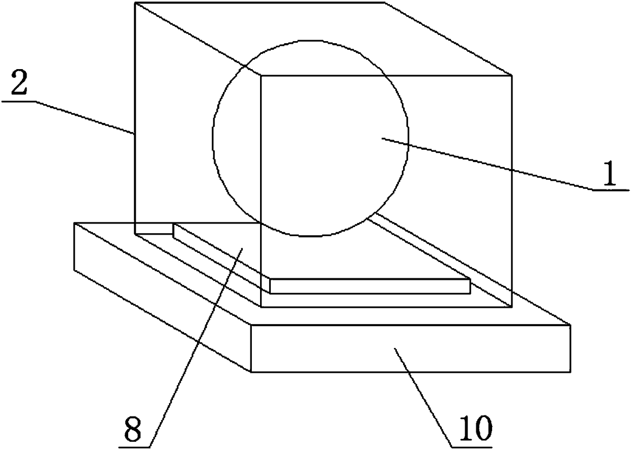
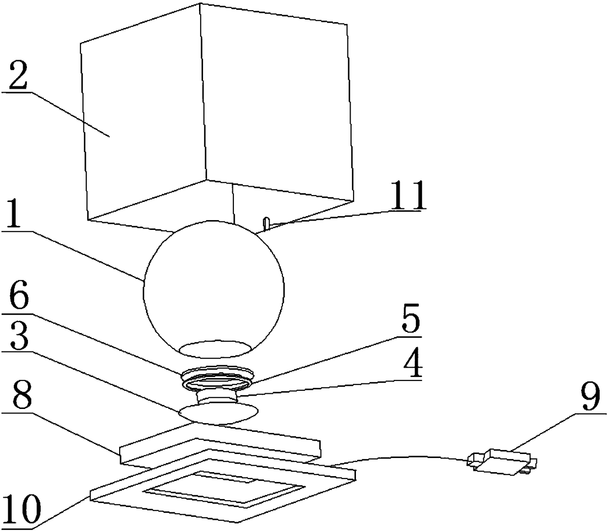
[0028] Such as Figure 1-4 As shown, a magnetic levitation 3D printed moon light includes:
[0029] The 3D printed sphere 1 has a hollow structure with an opening at its lower end, and the 3D printing material on its surface is an opaque light-transmitting material; the surface of the 3D printed sphere 1 has text, LOGO signs or pictures added.
[0030] Acrylic cover 2 is located on the outside of the 3D printing sphere 1, and its function is to protect the entire suspension from outside air flow and human hand touch, dustproof, and atmospheric appearance; the lower end side wall of the acrylic cover 2 is provided with a supply The threading hole 11 through which the wire of the magnetic levitation base power adapter 9 passes.
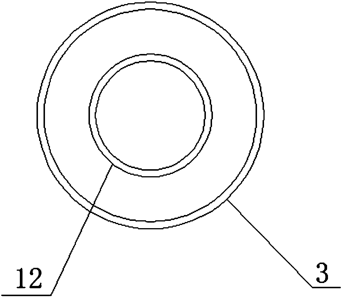
[0031] The 3D printed magnetic tray 3 is an inverted hat-shaped as a whole, and is connected to the 3D printed sphere 1 to form a spherical shape, and its inner middle part is connected with a limit ring 12; the 3D printed magnetic tray is fixed to the 3D printed sphere 1 by glue It is connected, and the surface is glued with a counterweight. It should be noted that the counterweight has no effect on the magnet, such as plastics, rocks, ceramics, etc., to make the overall center of gravity of the 3D printed magnetic tray 3 at the center point.
[0032] The permanent magnet set tray 4 is arranged on the inner side of the limit ring 12 and includes a concave magnet and a reverse pole circular magnet; it is used to generate a repulsive force with the magnetic levitation base chip set 8 so as to move upward when it approaches the magnetic levitation base chip set 8. Push, and then attracted by the four different-polar permanent magnets distributed around the center point of the magnetic levitation base chipset 8, so that the permanent magnet group tray 4 has a relative equilibrium position relative to the magnetic levitation base chipset 8, and the magnetic levitation base chipset 8 The inner electromagnet group will correct the permanent magnet group tray 4 in the relative position from four directions again, and the battery iron group can control the magnetic force by controlling the current, and switch the magnetic force to make the pair have a center point to rotate The force drives the permanent magnet assembly tray 4 to rotate, so that there is a centripetal force that makes the permanent magnet assembly tray 4 more stable in the relative position.
[0033] The receiving coil 5 is located on the upper side of the permanent magnet group tray 4, and it is an inverted circular coil; the receiving coil 5 is cut by the magnetic field generated by the magnetic levitation base chipset 8 when the coil is close to the coil and close to the magnetic levitation base chipset 8 A current is formed and reaches the luminous current value of the LED chip set, and the LED lamp emits light.
[0034] The receiving coil fixing cover 6 is located on the lower side of the receiving coil 5 and is used to fix the receiving coil 5. The stop ring 12 in the middle part of the 3D printed magnetic tray is used to fix the permanent magnet group tray 4, and 3D printing The brim part of the magnetic tray 3 is used to cooperate with the receiving coil fixing cover 6 to fix the receiving coil 5.
[0035] The LED light emitting chip set 7 is located on the upper side of the receiving coil fixing cover 6 and is electrically connected to the receiving coil 5.
[0036] The magnetic levitation base chip set 8 includes a permanent magnet set consisting of a central permanent magnet and four different pole permanent magnets, and the four different pole permanent magnets are evenly distributed around the central magnet. The central permanent magnet generates a repulsive force with the permanent magnet group tray 4 and lifts it up so that the permanent magnet group tray 4 is in a balanced position relative to the magnetic levitation base chipset 8; the magnetic levitation base chipset 8 also includes an electromagnet group, electromagnetic The iron group is used to correct the position of the permanent magnet group tray 4, and it can also control the magnetic force by changing the magnitude of the current, and switch the magnetic force between each other, so that the permanent magnet group tray 4 generates a central rotating force to drive the permanent magnet group tray 4 The magnet group tray 4 rotates, which in turn causes the 3D printed sphere 1 to rotate; the magnetic levitation base chipset 8 also includes an alternating current generator and a transmitting coil. When the transmitting coil is energized, an alternating magnetic field is generated, and the alternating magnetic field can cut the receiving coil 5. Make the LED light-emitting chip group 7 emit light.
[0037] The magnetic levitation base power adapter 9 is used to convert AC power into direct current and supply power to all electronic components in the magnetic levitation base chipset 8; the output voltage of the magnetic levitation base power adapter 9 is 12V, and the output current is based on the magnetic levitation base chipset Depending on the rated power of the internal electronic components.
[0038] The limit magnet group base 10 is located on the lower side of the magnetic levitation base chipset 8. Its upper end surface is provided with a first limit groove that matches the shape of the lower end of the acrylic cover 2, and its upper end surface is also provided with The second limiting slot with a matching shape at the lower end of the magnetic levitation base chipset 8 is described.
[0039] Although this article uses 3D printing sphere 1, acrylic cover 2, 3D printing magnetic tray 3, permanent magnet group tray 4, receiving coil 5, receiving coil fixing cover 6, LED light-emitting chip set 7, magnetic levitation base chip set 8, Terms such as the magnetic levitation base power adapter 9, the limit magnet group base 10, the threading hole 11 and the limit ring 12, but the possibility of using other terms is not excluded. These terms are used only to describe and explain the essence of the present invention more conveniently; to interpret them as any additional limitation is contrary to the spirit of the present invention.

PUM

no PUM

Description & Claims & Application Information

We can also present the details of the Description, Claims and Application information to help users get a comprehensive understanding of the technical details of the patent, such as background art, summary of invention, brief description of drawings, description of embodiments, and other original content. On the other hand, users can also determine the specific scope of protection of the technology through the list of claims; as well as understand the changes in the life cycle of the technology with the presentation of the patent timeline. Login to view more.

Similar technology patents

Pan-tilt control method and mobile platform

ActiveCN111656764AInterestingMeet the needs of robotics education
Owner:SZ DJI TECH CO LTD

Three-dimensional visual illusion display demonstration device

PendingCN106409095AInterestingmeet needs
Owner:CHANGCHUN CHINA OPTICAL SCI & TECH MUSEUM

Remote control method

InactiveCN101207748AInterestingSatisfy children's interest
Owner:KONKA GROUP

Classification and recommendation of technical efficacy words

  • Interesting
  • Improve viewing

Electronic frisbee shooting system

InactiveCN103252082AInterestingParticipatory and competitive
Owner:JINAN ZHONGBANG ELECTRONICS

Toy sound-control device

InactiveCN1640522AInterestingeasy to operate
Owner:SOUTH CHINA UNIV OF TECH

Audio and video playing method and device, electronic equipment and storage medium

ActiveCN110677727Aavoid black screenimprove viewing
Owner:BEIJING QIYI CENTURY SCI & TECH CO LTD

Camara sight with smart phone mount

ActiveUS20180245880A1improve viewingcost-effective
Owner:CAMPBELL ROBERT MARSHALL

Method and client for realizing network video live broadcast

InactiveCN106686471Aimprove viewingReduce network overhead
Owner:CHINA TELECOM CORP LTD
Why Eureka
Try Eureka