Medical apparatus and instrument drying equipment
A technology for drying equipment and medical equipment, applied in drying, drying machine, lighting and heating equipment and other directions, can solve the problems of less moisture residue, there will be moisture residue, slow drying speed, etc., and achieve fast drying speed , There will be no moisture residue, the effect of speeding up the drying speed
- Summary
- Abstract
- Description
- Claims
- Application Information
AI Technical Summary
Problems solved by technology
Method used
Image

Examples
Embodiment 1
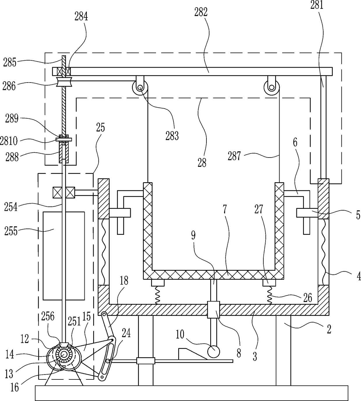
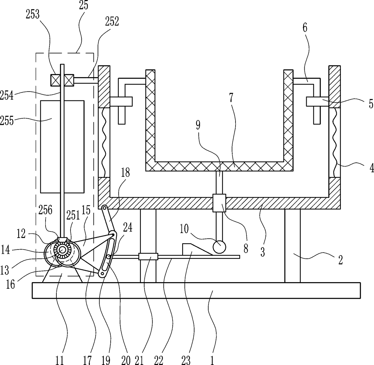
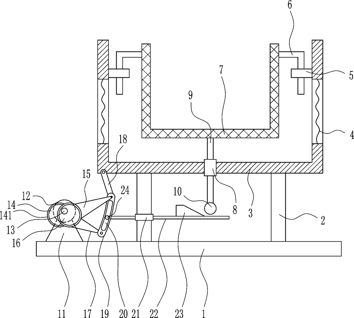
[0025] A medical device drying equipment, such as Figure 1-5 As shown, it includes a bottom plate 1, a pole 2, a frame body 3, a heating wire 4, a snap ring 5, an L-shaped guide rod 6, a screen frame 7, a first guide sleeve 8, a first straight guide rod 9, and a roller 10. , mounting seat 11, motor 12, first rotating shaft 13, first disc 14, ring 141, first triangular plate 15, second disc 16, second triangular plate 17, first connecting rod 18, arc plate 19, The second guide sleeve 21, the second straight guide rod 22, the wedge-shaped block 23 and the clamping shaft 24, the left and right sides of the top of the bottom plate 1 are provided with a strut 2, and the top of the strut 2 is connected with a frame body 3, and the frame body 3 is left and right. Heating wires 4 are provided in the middle of the two walls, and snap rings 5 are provided in the inner upper parts of the left and right walls of the frame body 3, and L-shaped guide rods 6 are inserted in the snap rings...
Embodiment 2
[0027] A medical device drying equipment, such as Figure 1-5 As shown, it includes a bottom plate 1, a pole 2, a frame body 3, a heating wire 4, a snap ring 5, an L-shaped guide rod 6, a screen frame 7, a first guide sleeve 8, a first straight guide rod 9, and a roller 10. , mounting seat 11, motor 12, first rotating shaft 13, first disc 14, ring 141, first triangular plate 15, second disc 16, second triangular plate 17, first connecting rod 18, arc plate 19, The second guide sleeve 21, the second straight guide rod 22, the wedge-shaped block 23 and the clamping shaft 24, the left and right sides of the top of the bottom plate 1 are provided with a strut 2, and the top of the strut 2 is connected with a frame body 3, and the frame body 3 is left and right. Heating wires 4 are provided in the middle of the two walls, and snap rings 5 are provided in the inner upper parts of the left and right walls of the frame body 3, and L-shaped guide rods 6 are inserted in the snap rings...
Embodiment 3
[0030] A medical device drying equipment, such as Figure 1-5 As shown, it includes a bottom plate 1, a pole 2, a frame body 3, a heating wire 4, a snap ring 5, an L-shaped guide rod 6, a screen frame 7, a first guide sleeve 8, a first straight guide rod 9, and a roller 10. , mounting seat 11, motor 12, first rotating shaft 13, first disc 14, ring 141, first triangular plate 15, second disc 16, second triangular plate 17, first connecting rod 18, arc plate 19, The second guide sleeve 21, the second straight guide rod 22, the wedge-shaped block 23 and the clamping shaft 24, the left and right sides of the top of the bottom plate 1 are provided with a strut 2, and the top of the strut 2 is connected with a frame body 3, and the frame body 3 is left and right. Heating wires 4 are provided in the middle of the two walls, and snap rings 5 are provided in the inner upper parts of the left and right walls of the frame body 3, and L-shaped guide rods 6 are inserted in the snap rings...
PUM
 Abstract
Description
Claims
Application Information
 - R&D
- Intellectual Property
- Life Sciences
- Materials
- Tech Scout
- Unparalleled Data Quality
- Higher Quality Content
- 60% Fewer Hallucinations
Browse by: Latest US Patents, China's latest patents, Technical Efficacy Thesaurus, Application Domain, Technology Topic, Popular Technical Reports.
© 2025 PatSnap. All rights reserved.Legal|Privacy policy|Modern Slavery Act Transparency Statement|Sitemap|About US| Contact US: help@patsnap.com