
Multifunctional pipeline stress testing device

A testing device, a multi-functional technology, applied in the direction of measuring device, using stable shear force to test material strength, using stable tension/pressure to test material strength, etc., can solve the problem that the stress test position cannot be flexibly adjusted, etc. problems, to achieve the effect of improving overall stability, improving efficiency, and solving single test functions

Pending Publication Date: 2018-12-18
GUANGDONG UNIV OF TECH
View PDF17 Cites 0 Cited by
  • Summary
  • Abstract
  • Description
  • Claims
  • Application Information

AI Technical Summary

Problems solved by technology

[0002] Most of the existing pipeline stress test devices can only perform stress tests on specific parts of the pipeline due to the structural limitations of the test devices. The stress test position cannot be flexibly adjusted due to the limitations of the test device structure, and the stress test of various parts of the pipeline cannot be flexibly realized.
At the same time, the shear force test of the pipeline requires the flexible height adjustment of the test device to be realized, and the test device in the prior art cannot meet the corresponding requirements.

Method used


Image

  • Multifunctional pipeline stress testing device
  • Multifunctional pipeline stress testing device

Examples


Embodiment 1

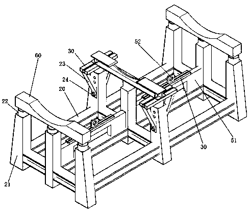
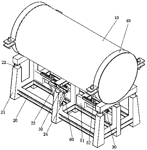
[0027] Such as figure 1 and as figure 2 As shown, the present invention provides a kind of multi-functional pipeline stress testing device, is provided with frame 20, is provided with fixing part 60 on frame 20, and fixing part 60 is arranged on the two ends of frame 20 and between two ends position, the fixing part 60 supports and fixes the pipeline 10 . The fixing part 60 is provided with an arc structure matching with the pipe 10 , and the arc structure improves the fit between the fixing part 60 and the pipe 10 .

[0028] Such as figure 1 As shown, a support member 21 is provided on the frame 20, and a lifting device 22 is provided on the support member 21. The lifting device 22 is a hydraulic lifting device 22, and the support is connected with the fixed part 60 through the lifting device 22, and the fixed part 60 is controlled to rise or fall. decline.

[0029] In this embodiment, three support members 21 are arranged side by side at or between both ends of the fram...

Embodiment 2

[0036]In this embodiment, three support members 21 arranged between the two ends of the frame 20 are provided side by side, and the support members 21 arranged on both sides are connected with the connecting rod 23, and the connecting rod 23 is connected with a slide rail 30, and the slide rail 30 can be connected with the lifting device 22 and can be displaced relative to the supporting member 21 under the action of the lifting device 22 .

[0037] After the slide rail 30 is displaced, the connecting rod 23 is fixedly connected to the support member 21 through the positioning screw 24 , so as to fix the position of the slide rail 30 relative to the support member 21 . The fixed part 60 is slidably connected to the slide rail 30 , the fixed part 60 can slide relative to the slide rail 30 , and the position of the fixed part 60 relative to the pipeline 10 can be adjusted to provide conditions for realizing the shear force test at different positions on the pipeline 10 .


PUM


Abstract

The invention relates to the technical field of stress testing devices, in particular to a multifunctional pipeline stress testing device which comprises a machine frame. The machine frame is providedwith a fixing part for fixing a pipeline, and the fixing part is connected with the machine frame through a lifting device; and the machine frame is provided with a positioning device which is matched with a tension meter to test the stress of the pipeline, the positioning device is slidably connected with a positioning part, and the position of the positioning part relative to the machine framecan be conveniently adjusted. The multifunctional pipeline stress testing device has the characteristics that the stress testing position can be adjusted flexibly, and stress testing is convenient.

Description

technical field [0001] The invention relates to the technical field of stress testing devices, and more particularly, to a multifunctional pipeline stress testing device. Background technique [0002] Most of the existing pipeline stress test devices can only perform stress tests on specific parts of the pipeline due to the structural limitations of the test devices. The stress test position cannot be flexibly adjusted due to the limitations of the test device structure, and the stress test of various parts of the pipeline cannot be flexibly realized. . At the same time, the shear force test of the pipeline can only be realized by flexible height adjustment of the test device, and the test device in the prior art cannot meet the corresponding requirements. Contents of the invention [0003] In order to overcome at least one defect of the above-mentioned prior art, the present invention provides a multifunctional pipe stress testing device, which has the characteristics of...

Claims


Application Information

Patent Timeline
Patent Type & Authority Applications(China)
IPC IPC(8): G01N3/12G01N3/24
CPCG01N3/12G01N3/24G01N2203/0019G01N2203/0048G01N2203/0025G01N2203/0274
Inventor 梁仕华何超郑杰罗泓冯德銮王志红
Owner GUANGDONG UNIV OF TECH
Learn More