
Radar sensor and vehicle collision early warning method

A radar sensor and vehicle controller technology, applied in the direction of reflection/re-radiation, utilization and re-radiation of instruments, radio waves, etc., can solve the problems of poor environmental adaptability, single function, complex structure of vehicle-mounted radar, etc., to achieve environmental adaptability Strong, the overall structure is simple, the effect of reducing the size

Pending Publication Date: 2018-12-18
WHST CO LTD
View PDF0 Cites 2 Cited by
  • Summary
  • Abstract
  • Description
  • Claims
  • Application Information

AI Technical Summary

Problems solved by technology

[0003] In view of this, the embodiment of the present invention provides a radar sensor and a vehicle collision early warning method to solve the problems of complex structure, single function and poor environmental adaptability of vehicle radar in the prior art

Method used


Image

  • Radar sensor and vehicle collision early warning method
  • Radar sensor and vehicle collision early warning method
  • Radar sensor and vehicle collision early warning method

Examples


Embodiment 1

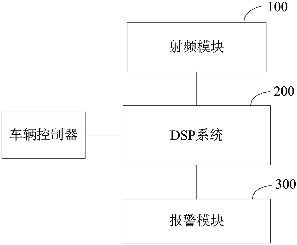
[0059] figure 1 A schematic structural diagram of a radar sensor according to this embodiment is shown, which is suitable for a vehicle. For ease of description, only parts related to this embodiment are shown.

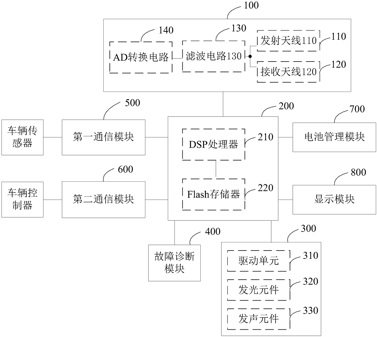
[0060] see figure 1 , the radar sensor includes a radio frequency module 100 , a DSP system 200 and an alarm module 300 .

[0061] Wherein, the radio frequency module 100 is connected with the DSP system 200, and the DSP system 200 is connected with the alarm module 300 and the vehicle controller.

[0062] The radio frequency module 100 is used to transmit the millimeter wave signal and receive the reflected wave signal reflected by the target; the DSP system 200 is used to provide the millimeter wave signal to the radio frequency module 100, and determine the relative position information of the target according to the reflected wave signal. When the relative position information is within the warning position range, an alarm driving signal is sent to the alarm mod...

Embodiment 2

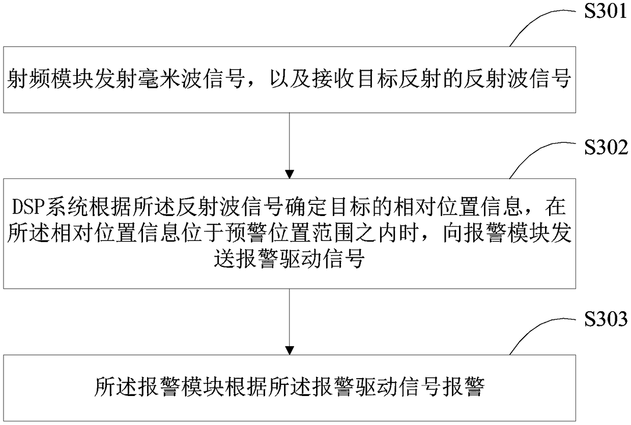
[0126] This embodiment provides a vehicle collision warning method, which is applicable to the radar sensor described in any one of the above embodiments. For details, see image 3 , a schematic diagram of a specific implementation process of a vehicle collision early warning method provided for this implementation, including:

[0127] In step S301, the radio frequency module transmits a millimeter wave signal and receives a reflected wave signal reflected by a target.

[0128] Step S302, the DSP system determines the relative position information of the target according to the reflected wave signal, and sends an alarm driving signal to the alarm module when the relative position information is within the warning position range.

[0129] Step S303, the alarm module alarms according to the alarm driving signal.

[0130] In one embodiment, the alarm driving signal includes: at least one of a sounding driving signal and a lighting driving signal.

[0131] The early warning posi...


PUM


Abstract

The invention is applicable to the technical field of an automotive radar and provides a radar sensor and a vehicle collision early warning method. The radar sensor comprises a radio frequency module,a DSP (Digital Signal Processing) system and an alarm module, wherein the radio frequency module is used for transmitting a millimeter wave signal and receiving a reflected wave signal reflected by atarget; the DSP system is applicable to be connected with a vehicle controller and is used for providing the millimeter wave signal for the radio frequency module, determining relative position information of the target according to the reflected wave signal and sending an alarm driving signal to the alarm module when the relative position information is within an early warning position range; and the alarm module is used for giving an alarm according to the alarm driving signal. The radar sensor can accurately and effectively detect the target around a vehicle and timely carry out collisionearly warning, and has the advantages of small size, simple structure and high environmental suitability.

Description

technical field [0001] The invention belongs to the technical field of vehicle radar, in particular to a radar sensor and a vehicle collision early warning method. Background technique [0002] The current vehicle-mounted radars include video recognition, lidar, ultrasonic radar, etc. Video recognition is seriously affected by light, and the recognition effect is poor when the line of sight is not ideal, making the radar environment adaptability of video recognition poor; Lidar is affected by light and weather Larger, foggy weather, rainy and snowy weather greatly reduce the performance of lidar, so millimeter wave radar is getting more and more attention. However, the existing millimeter-wave radar has problems such as large size, complex structure, and can only determine the target position, and its function is relatively single. Contents of the invention [0003] In view of this, an embodiment of the present invention provides a radar sensor and a vehicle collision war...

Claims


Application Information

Patent Timeline
IPC IPC(8): G01S13/93
CPCG01S13/931
Inventor 秦屹任玉东黄子月王悦宁高援朝
Owner WHST CO LTD
Learn More