Photoelectric linkage optical fiber system, virtual electronic label generation method and application

A technology of optical fiber system and electronic label, which is applied in the coupling of optical waveguide, optics, light guide, etc., can solve the problems of inapplicable installation of PCB board, difficulty in ensuring the quality of optical fiber use, and inability to use universal PCB board, so as to reduce the difficulty of installation and shorten the Effects of construction time and ease of parts replacement

Active Publication Date: 2020-10-09
FENGHUO COMM SCI & TECH CO LTD
View PDF4 Cites 0 Cited by
  • Summary
  • Abstract
  • Description
  • Claims
  • Application Information

AI Technical Summary

Problems solved by technology

Among them, when using the method of installing PCB in the optical fiber distribution module, due to the different port spacing of different types of optical fiber distribution modules, one type of PCB board cannot be used in common, resulting in that the method of installing PCB boards cannot be applied to different types of optical fiber distribution modules. line module; therefore, electronic tag technology solutions are mostly used, and when using electronic tag technology solutions, not only need to manually insert the optical fiber connector first, but also need to manually insert the electronic tag of the corresponding port during the construction process, thus increasing the The original construction steps, the construction process is more complicated, and the accuracy of manual operation is low, it is difficult to guarantee the quality of optical fiber

Method used


Image

  • Photoelectric linkage optical fiber system, virtual electronic label generation method and application
  • Photoelectric linkage optical fiber system, virtual electronic label generation method and application

Examples


Embodiment 1

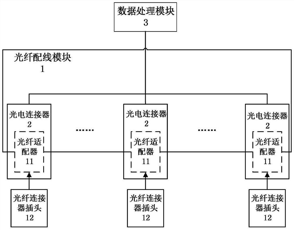
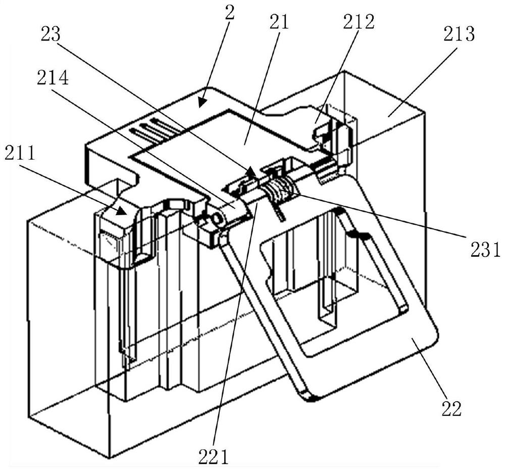
[0034] see figure 1 with figure 2 As shown, the embodiment of the present invention provides a photoelectric linkage optical fiber system, including an optical fiber distribution module 1, a photoelectric connector 2 and a data processing module 3. Preferably, the optical fiber distribution module 1 is an optical fiber distribution board or an optical fiber Distribution panel, the optical fiber distribution module 1 is provided with a plurality of optical fiber connectors, each optical fiber connector includes an optical fiber adapter 11 and two optical fiber connector plugs 12, the optical fiber adapter 11 is provided with two optical fiber connector plugs 12 Matching fiber optic connector interface.

[0035] The optical connector 2 is detachably arranged on the optical fiber adapter 11 , and the optical connector 2 is used for monitoring the presence information of the optical fiber connector plug 12 .

[0036] The data processing module 3 is connected with the photoelect...

Embodiment 2

[0041] On the basis of Embodiment 1, this embodiment provides a photoelectric linkage optical fiber system, the data processing module 3 includes a disk data processing module connected to the optical connector 2, an intermediate management module connected to the disk data processing module, and The main control panel module connected with the intermediate management module;

[0042] The process of generating a virtual electronic tag is:

[0043] The main control panel module is based on the equipment-related data of the photoelectric connector 2, the bus address assigned by the main control panel module to the intermediate management module, the port number of the disk data processing module connected to the intermediate management module, and the connection between the photoelectric connector 2 and the disk data processing module. The port number of the connection generates a unique ID number as a virtual electronic label identifying the port position of the photoelectric c...

Embodiment 3

[0045] On the basis of Embodiment 2, this embodiment provides an optical fiber system with photoelectric linkage. The main control panel module generates virtual electronic labels for the ports of multiple optical connectors 2, and finally forms a virtual electronic label containing multiple virtual electronic labels. Virtual electronic label library; the disk data processing module receives the device-related data of the photoelectric connector 2, the bus address assigned by the main control disk module to the intermediate management module, the port number of the disk data processing module connected to the intermediate management module, and the photoelectric connection The port number connecting the device and the disk data processing module generates a data packet and reports it to the main control panel module. The main control panel module matches the content of the data packet with the virtual electronic label library to determine the photoelectric connection where the i...


PUM


Abstract

The invention discloses a photoelectric linkage optical fiber system, a virtual electronic label generation method and its application, and relates to the field of optical fiber communication equipment, including an optical fiber wiring module, a photoelectric connector and a data processing module. The optical fiber wiring module is provided with a plurality of optical fibers connector, each fiber optic connector includes a fiber optic adapter and two fiber optic connector plugs, the fiber optic adapter is provided with two fiber optic connector interfaces matching the fiber optic connector plugs, the photoelectric connector is detachably arranged on the fiber optic adapter, and the photoelectric connection The device is used to monitor the in-position information of the optical fiber connector plug, the data processing module is connected with the photoelectric connector, and the data processing module is used to receive the in-position information monitored by the photoelectric connector. The present invention can detect the in-position status of the optical fiber connector interface. A corresponding virtual electronic label is generated for the fiber optic connector interface to complete the identity identification of the fiber optic connector interface.

Description

technical field [0001] The invention relates to the field of optical fiber communication equipment, in particular to a photoelectric linkage optical fiber system, a method for generating a virtual electronic label and an application thereof. Background technique [0002] With the continuous development of communication technology, optical fiber transmission is more and more used in communication systems, and optical fibers are mainly connected by optical fiber connectors. The fiber optic connector includes a fiber optic adapter and 2 fiber optic connector plugs, the fiber optic adapter is respectively connected to the 2 fiber optic connector plugs, and each fiber optic connector plug is connected to an optical fiber. In the optical fiber network, it is the most common way to connect the optical fiber through the optical fiber connector. [0003] Wherein, the optical fiber adapter is usually the main component of the mechanical connector in the ODN (Optical Distribution Netw...

Claims


Application Information

Patent Timeline
Patent Type & Authority Patents(China)
IPC IPC(8): G02B6/42G02B6/43G06K17/00
CPCG02B6/426G02B6/43G06K17/0029
Inventor 周鸣张智高浩
Owner FENGHUO COMM SCI & TECH CO LTD
Why Eureka
Try Eureka