
Calibration method for non-contact R-test measuring instrument using eddy current displacement sensor

A displacement sensor, non-contact technology, used in instruments, simulators, general control systems, etc., can solve the problems of the instrument itself is very difficult, difficult to achieve installation accuracy, and has a great impact on measurement accuracy, and achieve good measurement accuracy. , the effect of reducing manufacturing and use costs, and improving measurement efficiency

Active Publication Date: 2018-12-18
SOUTHWEST JIAOTONG UNIV
View PDF8 Cites 16 Cited by
  • Summary
  • Abstract
  • Description
  • Claims
  • Application Information

AI Technical Summary

Problems solved by technology

However, the structural processing and assembly of non-contact measuring instruments have a great impact on the measurement accuracy, and it is very difficult to improve the accuracy of the instrument itself
In addition, limited by the conditions of the measurement site, it is difficult for the instrument to be installed on the machine tool to achieve the installation accuracy during pre-calibration

Method used


Image

  • Calibration method for non-contact R-test measuring instrument using eddy current displacement sensor
  • Calibration method for non-contact R-test measuring instrument using eddy current displacement sensor
  • Calibration method for non-contact R-test measuring instrument using eddy current displacement sensor

Examples


Embodiment Construction

[0038] The present invention will be described in further detail below in conjunction with the accompanying drawings and specific embodiments.

[0039] (1) Structure description of non-contact R-test measuring instrument:

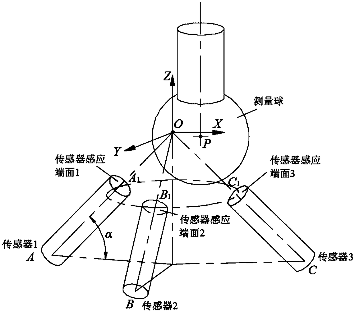
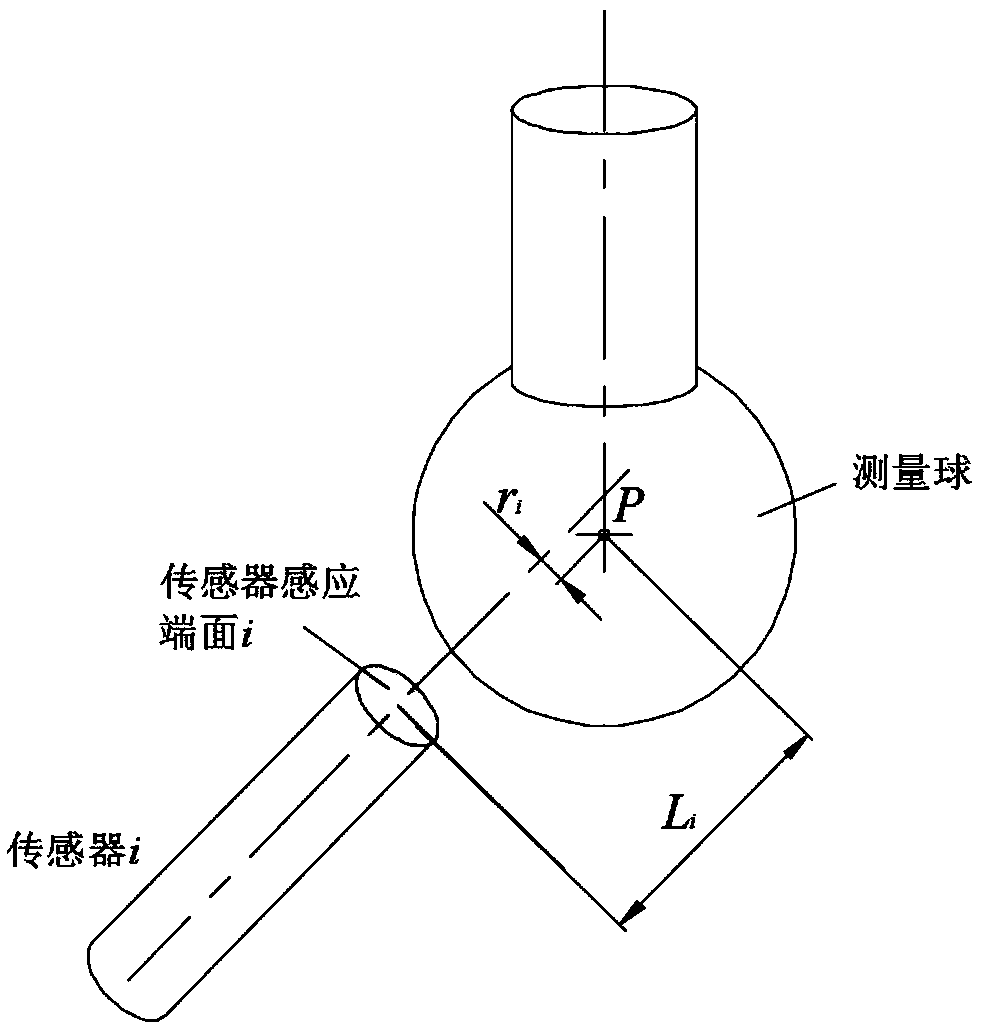
[0040] The structural model of the non-contact R-test measuring instrument is as follows figure 1As shown, it mainly includes three non-contact eddy current displacement sensors uniformly distributed and a standard measuring ball. According to the shortest distance spatial position relationship between the sensing plane of the sensor and the measuring ball, the coordinate calculation of the center point P of the measuring ball is performed.

[0041] figure 1 Medium AA 1 、BB 1 、CC 1 for the 3 sensor axes (A 1 , B 1 、C 1 is the center point of the sensing plane of the three sensors, A, B, and C are the bottom center points of the three sensors), and the radius of the end of the sensor is R 探 The induction plane circle of , the radius of the measuring...


PUM


Abstract

The invention discloses a calibration method for a non-contact R-test measuring instrument using an eddy current displacement sensor. Calibration of a measuring coordinate system and calibration of adisplacement sensor plane are included. A measuring ball is installed on a machine tool spindle, the bottom face of a measuring instrument is placed on a machine tool working table, the spindle is moved so that the measuring ball center is roughly located at the intersection point of the axes of three displacement sensors, a measuring coordinate system origin of the R-test measuring instrument iscalibrated, and the direction of a machine tool coordinate system is taken as the direction of the measuring coordinate system; the spindle is moved to make a ball head move to different coordinate points. Calibration of the non-contact R-test measuring instrument sensor reaction plane is completed according to the distances from the coordinate points to a sensor reaction plane. According to the calibration method for the non-contact R-test measuring instrument using the eddy current displacement sensor, the influence of installation errors of the non-contact R-test measuring instrument in processing and assembling and on the machine tool on the measuring accuracy can be greatly reduced, so that the manufacturing and using costs of the instrument are lowered, and the measuring accuracy andefficiency are improved.

Description

technical field [0001] The invention relates to the technical field of error measurement of numerical control machine tools, in particular to a non-contact R-test measuring instrument calibration method using an eddy current displacement sensor. Background technique [0002] With the improvement of machining accuracy, the geometric error measurement of five-axis CNC machine tools is becoming more and more important. For the geometric error measurement of the rotation axis of five-axis CNC machine tools, the measuring instruments usually used are ballbar and laser interferometer. However, these measuring instruments are not dedicated to the error measurement of the rotating shaft, and have disadvantages such as low efficiency and difficulty in eliminating installation errors. Compared with the shortcomings of the above-mentioned instruments, the R-test measuring instrument has the advantages of simple structure and high measurement efficiency, and can better meet the geometri...

Claims


Application Information

Patent Timeline
IPC IPC(8): G05B19/401
CPCG05B19/401G05B2219/34242
Inventor 江磊丁国富张剑彭炳康邹益胜马术文黎荣
Owner SOUTHWEST JIAOTONG UNIV
Learn More