Near-field sparse antenna array optimization method based on L1 norm constraint

A technology of antenna array direction and L1 norm, which is applied in design optimization/simulation, electrical digital data processing, special data processing applications, etc., can solve the problem of focus shift, near-field sparse antenna array optimization algorithm cannot accurately control the near-radiation Field pattern side lobe level and other issues, to achieve the effect of controllable side lobe level and solve focus shift

Active Publication Date: 2018-12-18
UNIV OF ELECTRONIC SCI & TECH OF CHINA
View PDF9 Cites 11 Cited by
  • Summary
  • Abstract
  • Description
  • Claims
  • Application Information

AI Technical Summary

Problems solved by technology

[0005] The present invention aims at the problem that the above-mentioned existing near-field sparse antenna array optimization algorithm cannot accurately control the sidelobe level of the r

Method used


Image

  • Near-field sparse antenna array optimization method based on L1 norm constraint
  • Near-field sparse antenna array optimization method based on L1 norm constraint
  • Near-field sparse antenna array optimization method based on L1 norm constraint

Examples


Embodiment Construction

[0028] Embodiments of the present invention are described below through specific examples, and those skilled in the art can easily understand other advantages and effects of the present invention from the content disclosed in this specification. The present invention can also be implemented or applied through other different specific implementation modes, and various modifications or changes can be made to the details in this specification based on different viewpoints and applications without departing from the spirit of the present invention.

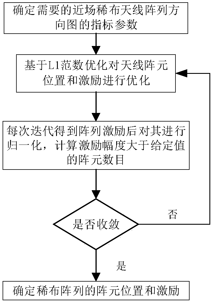
[0029] A near-field sparse antenna array optimization method based on compressed sensing and convex optimization, comprising the following steps:

[0030] Step 1. Determine the index parameters of the required near-field sparse antenna array pattern: according to the given array aperture size, set a planar array with evenly distributed array elements, and the array element spacing is between 0.01λ and 0.5λ Select, where λ is the worki...


PUM


Abstract

The invention provides a near-field sparse antenna array optimization method based on L1 norm constraint, which comprises the following steps: 1. determining the index parameters of the needed near-field sparse antenna array pattern; 2. determining the index parameters of the near-field sparse antenna array pattern. 2, using the L1 norm constraint theory to carry out iterative solution on the array element position and corresponding excitation; 3, normalizing the array excitation obtained by each iteration, and calculating the number of array elements whose excitation amplitude is greater thana given value; 4, judging whether that numb of units of three successive iterations is equal, if equal, the algorithm converges to obtain the final array topology and corresponding excitation. The invention obtains the sparse near-field antenna array topology and corresponding excitation based on the L1 norm minimization. Compared with the traditional method, the sidelobe level is controllable, and the problem of focus shift in the near-field focusing technology is solved at the same time.

Description

technical field [0001] The invention belongs to the technical field of antennas, in particular to a method for forming a pattern of a sparse near-field antenna array, in particular to a method for forming a pattern of a pattern of a sparse near-field antenna array based on L1 norm constraints. Background technique [0002] Due to the wide application range of beamforming in the radiative near-field region, the beamforming technology in the radiative near-field region has received more and more attention. Its specific applications cover various fields such as industry and medicine, including microwave imaging, remote sensing, wireless energy transmission, radio frequency identification, microwave hyperthermia, etc. Generally speaking, if you want to have better near-field radiation characteristics, such as smaller focal spot size, lower sidelobes, and near-field beam formation with responsible shape, it means that you need a larger aperture and more antennas An antenna array...

Claims


Application Information

Patent Timeline
IPC IPC(8): G06F17/50
CPCG06F30/00G06F30/20Y02D30/70
Inventor 程钰间黄子轩林宏声樊勇宋开军林先其张波
Owner UNIV OF ELECTRONIC SCI & TECH OF CHINA
Why Eureka
Try Eureka