Electronic tag that monitors bolt looseness

An electronic label and bolt loosening technology, which is applied to record carriers, instruments, computing and other directions used by machines, can solve the problems of difficult construction, loss of life and property, and high processing costs, so as to improve labor efficiency, prevent oil pollution, and improve The effect of work efficiency

Inactive Publication Date: 2018-12-18
TIANJIN YUNTUO NETWORK TECH CO LTD
View PDF4 Cites 8 Cited by
  • Summary
  • Abstract
  • Description
  • Claims
  • Application Information

AI Technical Summary

Problems solved by technology

[0002] As a fastener, bolts are widely used in various fields. Its biggest advantage is that it is easy to disassemble and assemble, but there is also a risk of loosening. For example, there are tens of thousands of bolts on a train. If any one falls off, it will cause incalculable damage. loss of life and property
[0003] Using the bolt loosening monitoring method based on image recognition, it cannot be recognized when oil is accumulated on the surface of the bolt, and the lens of image recognition must face the bolt. However, in actual use, bolts are installed at different angles and the detection speed is slow, which also makes image recognition technology unfeasible.
Bolt loosening monitoring using piezoelectric sensing elements is based on measuring the impedance value change of piezoelectric sensing elements to realize bolt loosening monitoring. This method needs to measure impedance values, and the equipment cost is high and the structure is complicated, which is not conducive to large-scale automatic collection and monitoring.
[0004] Smart bolts using fiber grating sensors, bolts need radial openings, high processing costs, and fiber grating sensors require wiring, difficult construction, difficult maintenance, and poor reliability

Method used


Image

  • Electronic tag that monitors bolt looseness
  • Electronic tag that monitors bolt looseness
  • Electronic tag that monitors bolt looseness

Examples


Embodiment Construction

[0036] The present invention will be further described below in conjunction with the accompanying drawings and specific embodiments, but not as a limitation of the present invention.

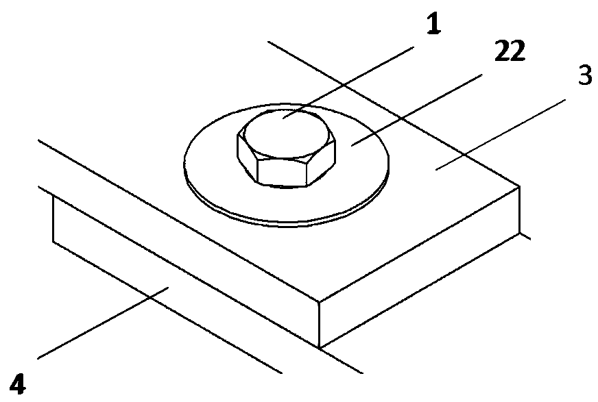
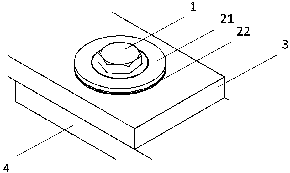
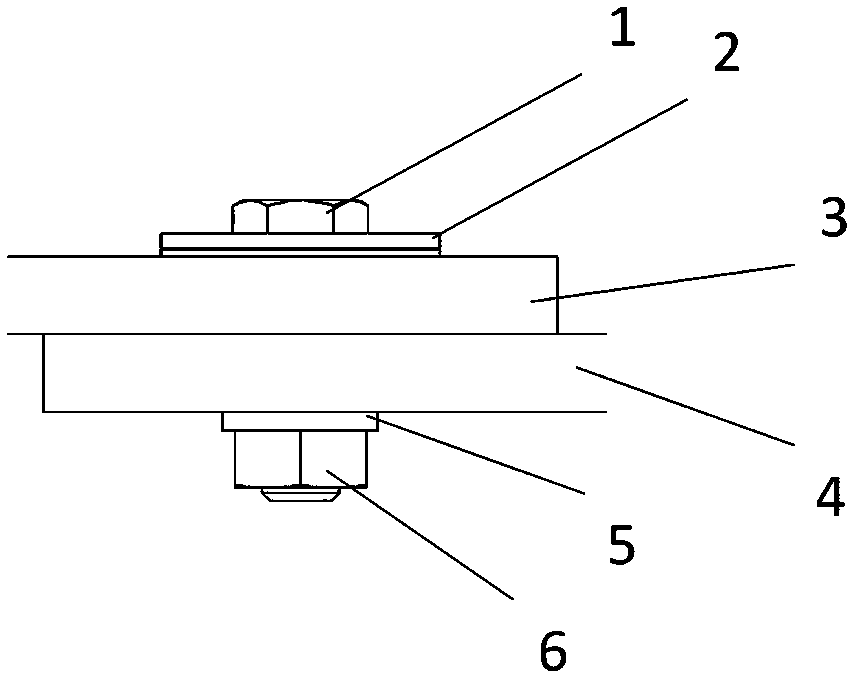
[0037] Such as Figure 4 As shown, an electronic tag 2 for monitoring bolt looseness mainly includes an electronic tag body 21 and an electronic tag base 22 .

[0038] The electronic tag body 21 includes a counterbore 212 , a non-fixed part 218 , a fragile area 211 , a fixed part 217 and a radio frequency circuit.

[0039] Preferably, the electronic tag main body 21 is made of ABS thermoplastic polymer material.

[0040] Such as figure 1 As shown, the external dimensions of the counterbore 212 are determined according to the external dimensions of the bolt head, so as to ensure that when the bolt 1 rotates, the non-fixed part 218 is driven to rotate under force.

[0041] Such as Image 6 As shown, the radio frequency circuit includes a radio frequency chip 213 , an antenna 214 and an anti-ta...


PUM


Abstract

An electronic tag 2 for monitoring bolt looseness includes an electronic tag body 21 and an electronic tag base 22. The electronic tag body 21 includes a counterbore 212, a non-stationary portion 218,a fragile region 211, a stationary portion 217, and a radio frequency circuit. Between the non-stationary portion 218 and the stationary portion 217, only a portion of the anti-disassembly thread 215and a small numb of other portions are connected to form the fragile region 211. The radio frequency circuit includes a radio frequency chip 213, an antenna 214, and a disconnect-proof wire 215. Whenthe non-stationary portion 218 is subjected to a rotational force causing the fragile region 211 to break, the detachment-proof wire 215 is also broken. The radio frequency chip 213 in the radio frequency circuit may store the tag number, and when the anti-disconnect wire 215 is disconnected, the disconnect signal and the tag number are uploaded to the monitoring platform through the tag reader/writer. The invention has the advantages of simple structure, small volume, no power supply, accurate monitoring and large area application.

Description

technical field [0001] The invention relates to bolt loosening monitoring, in particular to an electronic tag for monitoring bolt loosening. Background technique [0002] As a kind of fastener, bolt is widely used in various fields. Its biggest advantage is that it is convenient for disassembly and assembly, but there is also a risk of loosening. For example, there are tens of thousands of bolts on a train. If any one falls off, it will cause immeasurable damage. Loss of life and property. [0003] Using the bolt loosening monitoring method based on image recognition, it cannot be recognized when oil is accumulated on the surface of the bolt. The image recognition lens must face the bolt. However, in actual use, the bolts are installed at different angles and the detection speed is slow, which also makes the image recognition technology unfeasible. Bolt loosening monitoring using piezoelectric sensing elements is based on measuring the impedance value change of piezoelectri...

Claims


Application Information

Patent Timeline
Patent Type & Authority Applications(China)
IPC IPC(8): G06K19/077
CPCG06K19/0772G06K19/07798
Inventor 杨曼莫文凯黄红叶
Owner TIANJIN YUNTUO NETWORK TECH CO LTD
Why Eureka
Try Eureka