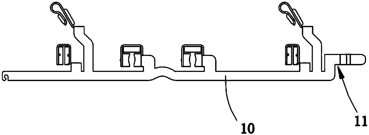
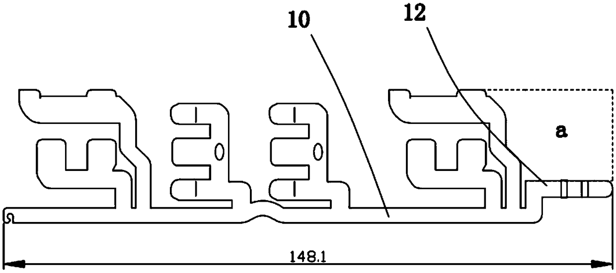
Copper bar for socket, socket and processing technology of copper bar for socket
A processing technology and copper strip technology, applied in the socket and socket copper strip processing technology, socket copper strip field, can solve the problems of low material utilization, long copper strip length, waste waste, etc., to reduce production costs, reduce The effect of waste, reducing the amount of removal
- Summary
- Abstract
- Description
- Claims
- Application Information
AI Technical Summary
Problems solved by technology
Method used
Image
Examples
Embodiment 1
[0057] Please refer to Figure 4-Figure 6 ,in, Figure 4 Schematic diagram of the structure of the copper strip for the socket provided in Embodiment 1 of the present invention; Figure 5 It is a structural schematic diagram of another viewing angle of the copper bar for the socket provided by Embodiment 1 of the present invention; Image 6 It is a schematic diagram of the unfolded structure of the copper strip for the socket provided by Embodiment 1 of the present invention. The copper strip 100 for the socket comprises a copper strip main body 1 and several socket sleeves 2 connected with the copper strip main body 1, one end of the copper strip main body 1 is extended to form a molding 3, and the molding 3 is bent and arranged relative to the length direction of the copper strip main body 1 , the molded part 3 is processed to form a bent structure 4, and the bent structure 4 is connected to the terminal.
[0058] In the embodiment of the present invention, there is one c...
Embodiment 2
[0071] Please refer to Image 6 , Figure 8 as well as Figure 9 ,in, Figure 8 Schematic diagram of the structure of the copper strip for the socket provided in Embodiment 2 of the present invention; Figure 9 It is a structural schematic diagram of another viewing angle of the copper strip for socket provided by Embodiment 2 of the present invention. The copper bar 200 for the socket of the present embodiment is substantially the same as the copper bar 100 for the socket of the first embodiment, and the molded part 3 is also bent and arranged relative to the length direction of the copper bar main body 1, and the unfolded state of the copper bar 200 for the socket is the same as Image 6 same. The difference from Embodiment 1 is that in this embodiment, the molded part 3 is folded along the two folded sides in turn to form the bent portion 41 . The insertion part 42 is formed by bending and extending one end of the bending part 41 , and the insertion part 42 is arranged...
Embodiment 3
[0077] Please refer to Image 6 , Figure 10 as well as Figure 11 ,in, Figure 10 Schematic diagram of the structure of the copper strip for the socket provided in Embodiment 3 of the present invention; Figure 11 It is a structural schematic diagram of another viewing angle of the copper bar for socket provided by Embodiment 3 of the present invention. The copper bar 300 for the socket of the present embodiment is substantially the same as the copper bar 100 for the socket of the first embodiment, and the molded part 3 is also bent and arranged relative to the length direction of the copper bar main body 1, and the unfolded state of the copper bar 300 for the socket is the same as Image 6 same. Compared with Embodiment 1, the difference lies in the bending structure 4 . The molded part 3 in this embodiment is bent to form a bent portion 41 , and the end of the insertion portion 42 is arranged parallel to the copper bar main body 1 .
[0078] In this embodiment, the mo...
PUM
| Property | Measurement | Unit |
|---|---|---|
| length | aaaaa | aaaaa |
| length | aaaaa | aaaaa |
Abstract
Description
Claims
Application Information
 - R&D
- Intellectual Property
- Life Sciences
- Materials
- Tech Scout
- Unparalleled Data Quality
- Higher Quality Content
- 60% Fewer Hallucinations
Browse by: Latest US Patents, China's latest patents, Technical Efficacy Thesaurus, Application Domain, Technology Topic, Popular Technical Reports.
© 2025 PatSnap. All rights reserved.Legal|Privacy policy|Modern Slavery Act Transparency Statement|Sitemap|About US| Contact US: help@patsnap.com


