Air bag, watch-type sphygmomanometer, portable blood pressure module and vital signal monitoring instrument
A watch type, sphygmomanometer technology, applied in vascular evaluation, medical science, sensors, etc., can solve the problems of inaccurate blood pressure measurement and inconsistent pulse signal strength, and achieve the effect of improving accuracy and reducing changes
- Summary
- Abstract
- Description
- Claims
- Application Information
AI Technical Summary
Problems solved by technology
Method used
Image

Examples
Embodiment 1
[0049] This embodiment provides a watch-type electronic sphygmomanometer.
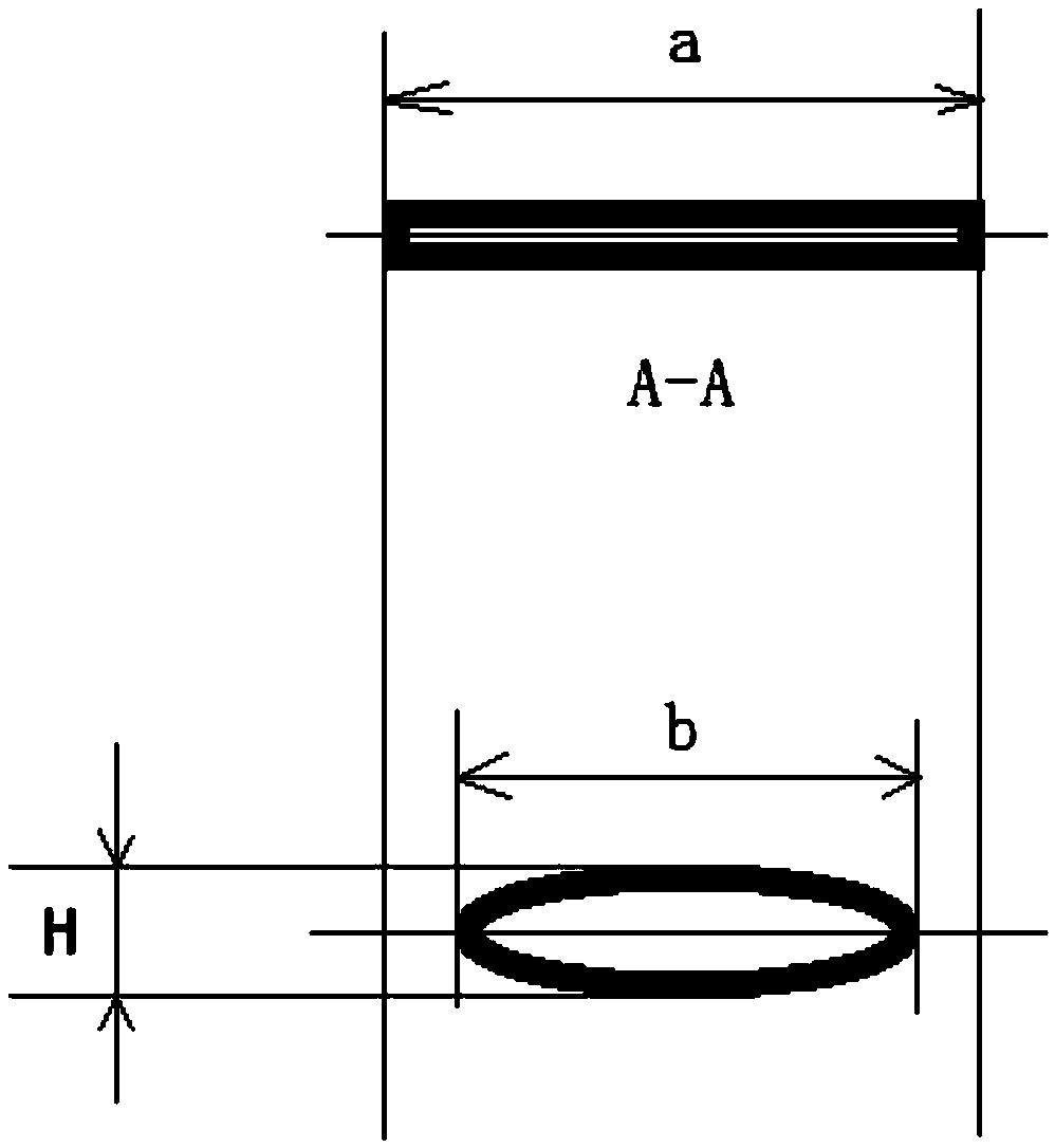
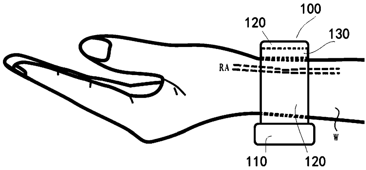
[0050] Please refer to figure 2 , the watch-type electronic sphygmomanometer 100 can be worn on the user's wrist W like a watch. It generally includes an inflatable unit (not shown in the figure) and an air bag 130 , the inflatable unit communicates with the air bag 130 and can inflate the air bag 130 . When the sphygmomanometer measures blood pressure, it only needs to bind the airbag 130 directly against the limb without using a cloth bag, which effectively improves hygiene, comfort and aesthetics.
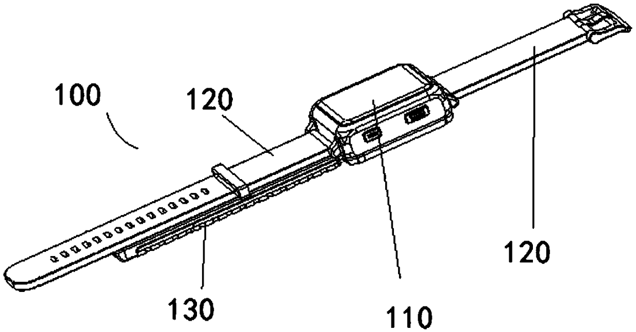
[0051] Of course, please refer to Figure 2-4 , the watch-type electronic sphygmomanometer 100 generally also includes a body 110 and a strap 120 . In addition to the inflation unit, the main body 110 also has other components such as a pressure sensor and a control unit. The strap 120 is mounted on the body 110 for easy wearing. Both the inflation unit and the pressure sensor are in communication ...
Embodiment 2
[0073] Embodiment 2 provides another watch-type sphygmomanometer.
[0074] In this embodiment, one end of the airbag 130 has a mounting structure, and the airbag 130 is fixedly connected to the main body through the mounting structure. In this structure, the airbag 130 can be completely fixed by the main body, or fixed by the main body and the strap 120 at the same time. Wherein, the airbag 130 can adopt the same structure as the first embodiment or a modified structure from the first embodiment.
[0075] Please refer to Figure 9 with 10 , In one embodiment, the installation structure includes a buckle 135 , and the airbag 130 is detachably fixed on the main body 110 through the buckle 135 .
[0076] Specifically, the airbag 130 can have a connecting piece 132 , and the connecting piece 132 can be fixedly installed in the airbag 130 , for example, can be fixedly installed on the upper wall 132 . The buckle 135 is fixedly disposed on the connecting member 132 , and the mai...
Embodiment 3
[0080] The third embodiment provides a portable blood pressure measurement module, which can be stored at ordinary times, and can be detachably installed on the wrist wearer for blood pressure measurement when blood pressure measurement is required. The wrist wearer includes various items that can be worn on the wrist W such as watches, bracelets, and wristbands.
[0081] Please refer to Figure 12-15 , the portable blood pressure measurement module 200 includes a body 210, an air bag 230 and a fixing structure 220 for detachably installing the body 210 on a wrist wearer. The body 210 has an air charging unit, a pressure sensor, a control unit and other related components. Here, the introduction of the airbag 230 and its related connections will be focused on, and other structures will not be described in detail here because they do not involve the main improvement of this embodiment.
[0082] Both the inflatable unit and the pressure sensor are in communication with the air...
PUM
 Abstract
Description
Claims
Application Information
 - Generate Ideas
- Intellectual Property
- Life Sciences
- Materials
- Tech Scout
- Unparalleled Data Quality
- Higher Quality Content
- 60% Fewer Hallucinations
Browse by: Latest US Patents, China's latest patents, Technical Efficacy Thesaurus, Application Domain, Technology Topic, Popular Technical Reports.
© 2025 PatSnap. All rights reserved.Legal|Privacy policy|Modern Slavery Act Transparency Statement|Sitemap|About US| Contact US: help@patsnap.com