Novel workbench for steel bar cutting machine

A cutting machine and workbench technology, applied in the field of construction engineering, can solve problems such as troublesome cleaning, easy to be scalded, and single function, and achieve the effect of improving shock absorption and reducing labor intensity

Active Publication Date: 2018-12-21
GUIZHOU UNIV
View PDF10 Cites 6 Cited by
  • Summary
  • Abstract
  • Description
  • Claims
  • Application Information

AI Technical Summary

Problems solved by technology

[0004] The purpose of the present invention is to solve the single function in the prior art. When cutting the steel bar, the operator needs to hold the cutting machine to cut it, which will cause arm pain after a long time. If you move forward to one end, your hands will be stained with steel oil, which is difficult to clean. There is no cooling function. When the steel bar is cut, the temperature is very high, and it is easy to be burned if you are not careful. In addition, it is troublesome to clean, and the workbench will vibrate a lot when cutting. There is no improvement in this situation, and a new type of workbench for steel bar cutting machine is proposed.

Method used


Image

  • Novel workbench for steel bar cutting machine
  • Novel workbench for steel bar cutting machine
  • Novel workbench for steel bar cutting machine

Examples


Embodiment Construction

[0022] The following will clearly and completely describe the technical solutions in the embodiments of the present invention with reference to the accompanying drawings in the embodiments of the present invention. Obviously, the described embodiments are only some, not all, embodiments of the present invention.

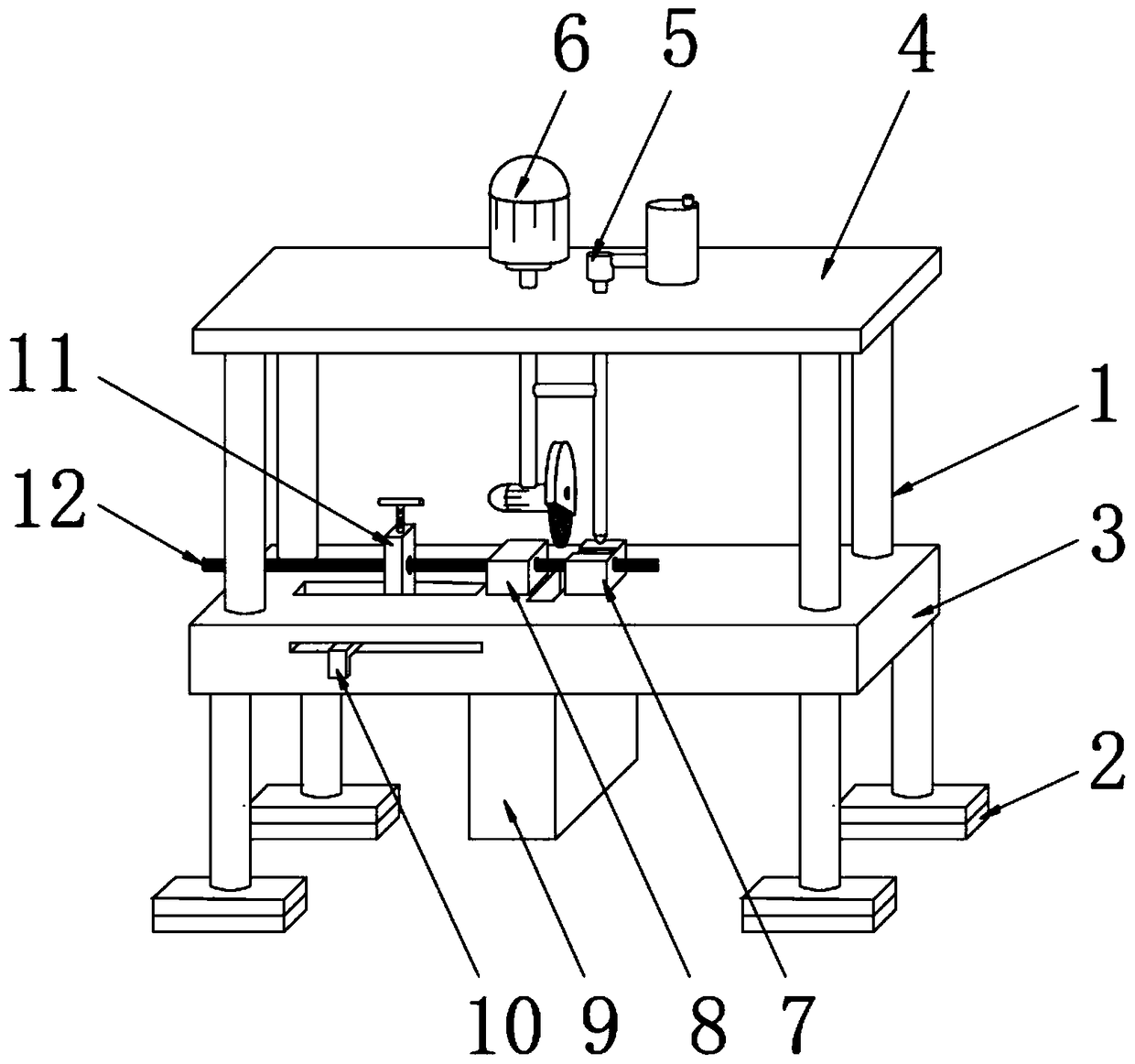
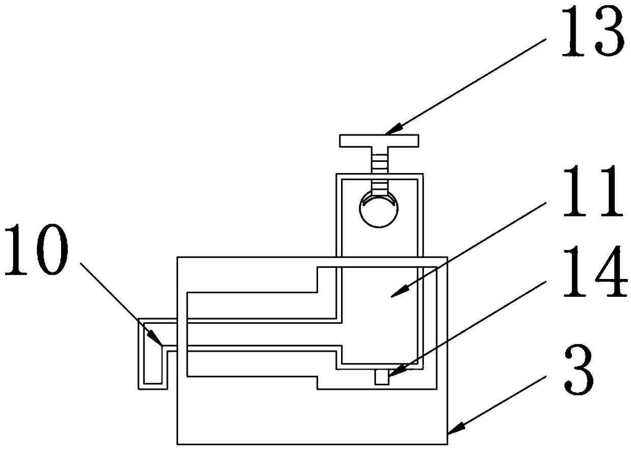
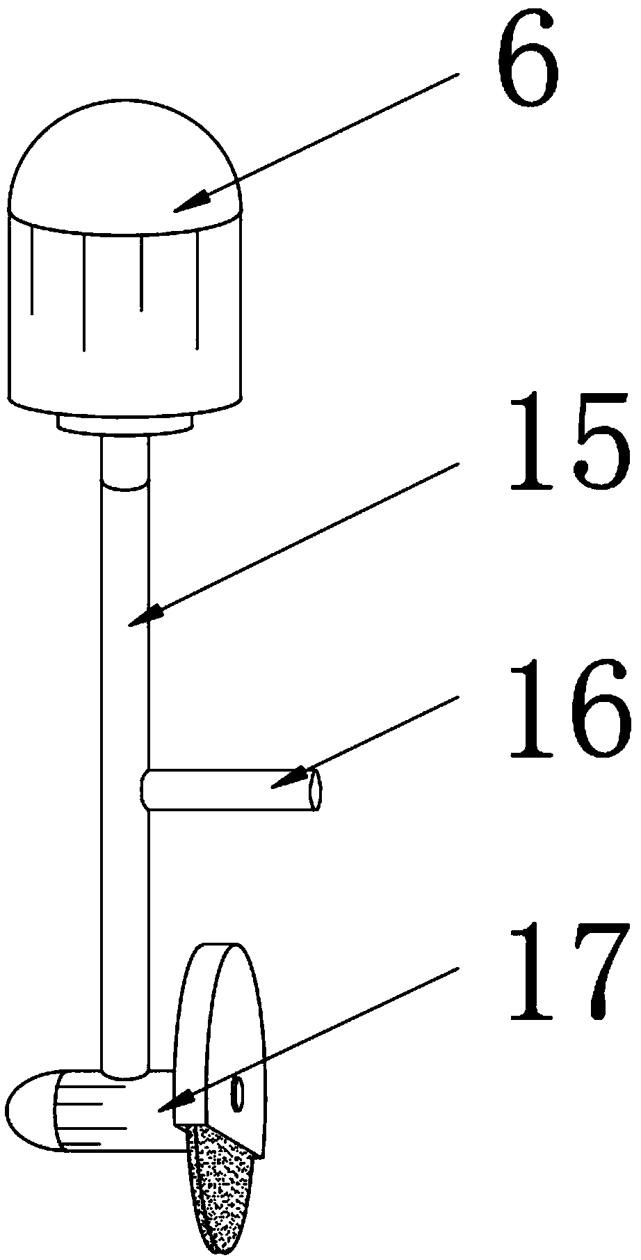
[0023] refer to Figure 1-5 , a new workbench for a steel bar cutting machine, comprising a support column 1, the lower end of the support column 1 is fixedly connected with a shock absorber 2, and the outer surface of the support column 1 is socketed with a cutting table 3, and the upper end of the support column 1 is fixed A top platform 4 is installed, the upper surface of the top platform 4 is embedded with a water injector 5, and the upper surface of the top platform 4 is embedded with a cylinder 6 near the side of the water injector 5, and the upper surface of the cutting table 3 is fixed. The first fixed block 7, and the upper surface of the cutting table 3 is...


PUM


Abstract

The invention discloses a novel workbench for a steel bar cutting machine, comprising a support column. A lower end of the support column is fixedly connected with a shock absorber, and an outer surface of the support column is sleeved and mounted with a cutting table. A top platform is fixedly mounted on a top end of the support column. A water injector is mounted on an upper surface of the top platform in an embedded mode, and a cylinder is mounted at one side of the upper surface, close to the water injector, of the top platform in the embedded mode. The upper surface of the cutting table is fixedly provided with a first fixing block, and a second fixing block is fixedly disposed at one side of the upper surface, close to the first fixing block, of the cutting table. According to the novel workbench for the steel bar cutting machine, the cutting machine can be driven to reciprocate up and down by arranging an air cylinder, so that cutting of steel bars is achieved automatically, theuse of a handheld cutting machine is avoided, the labor intensity is reduced, and the steel bar swarf generated during cutting can fall into a collecting box by arranging the collecting box, therebyavoiding soiling the cutting table.

Description

technical field [0001] The invention relates to the technical field of construction engineering, in particular to a novel steel bar cutting machine workbench. Background technique [0002] The working table of the steel bar cutting machine is an indispensable piece of equipment in construction engineering. When the steel bar needs to be processed in the building, it is necessary to place the steel bar on the working table of the steel bar cutting machine for cutting. [0003] However, the current workbench of the cutting machine in the building has a single function. When the operator cuts the steel bar, he needs to hold the cutting machine to cut it. After a long time, it will cause sore arms. When cutting, he needs to hold the steel bar at each end and move forward. At one end, the hand will be stained with steel oil, which is difficult to clean. There is no cooling function. When the steel bar is cut, the temperature is very high, and it is easy to be burned if you do not...

Claims


Application Information

Patent Timeline
Patent Type & Authority Applications(China)
IPC IPC(8): B21F11/00
CPCB21F11/00
Inventor 张玉涛杜斌郭仔翔车小林沈明轩
Owner GUIZHOU UNIV
Why Eureka
Try Eureka