Gear polishing device

A technology for gears and mounting columns, which is applied to gear teeth manufacturing devices, belts/chains/gears, gear teeth, etc. It can solve the problems of reducing the use effect, consuming a lot of labor and time, and low grinding efficiency, so as to achieve the effect of high efficiency

Active Publication Date: 2018-12-21
安徽致精机电科技有限公司
View PDF8 Cites 5 Cited by
  • Summary
  • Abstract
  • Description
  • Claims
  • Application Information

AI Technical Summary

Problems solved by technology

[0002] A gear is a mechanical element with gears on the rim that continuously meshes to transmit motion and power. It is widely used in the transmission field. The gear is one of the essential components in the gearbox. The quality of the gear determines the stability of the transmission. In the process of gear processing, there will be burrs on the teeth of the gears. If they are not removed, the use effect will be greatly reduced in practical applications, such as reducing the product quality of the reducer. There are few machines, and most of them are done manually, which takes a lot of labor and time, and the grinding efficiency is low

Method used


Image

  • Gear polishing device
  • Gear polishing device

Examples


Embodiment Construction

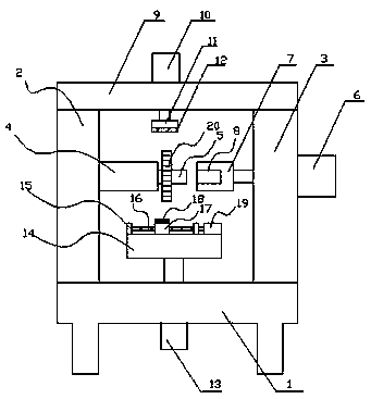
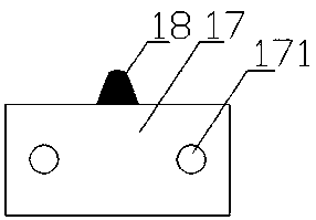
[0014] Such as figure 1 , 2 As shown, the present invention discloses a gear grinding device, comprising: a chassis 1, a left support plate 2, a right support plate 3, a cylindrical block 4, a mounting column 5, a right cylinder 6, a limit block 7, and a cylindrical cavity 8. Top plate 9, upper cylinder 10, connecting plate 11, block 12, lower cylinder 13, abutment 14, fixed block 15, guide rod 16, slider 17, grinding head 18, automatic reciprocating cylinder 19, the left support The plate 2 and the right support plate 3 are respectively fixed vertically on the left and right sides of the upper end surface of the chassis 1, and a cylindrical block 4 is horizontally fixed on the top of the right end surface of the left support plate 2, and the left end of the installation column 5 is connected with the right end of the cylindrical block 4. The center of the surface is fixed, the installation column 5 is set horizontally, the right cylinder 6 is installed on the right end surfa...


PUM


Abstract

The invention discloses a gear polishing device. The gear polishing device comprises an underframe, a left supporting plate, a right supporting plate, a cylindrical block, an erection column, a rightgas cylinder, a limiting block, a cylindrical cavity, a top plate, an upper gas cylinder, a connecting plate, a clamping block, a lower gas cylinder, a base platform, fixed blocks, guide rods, a sliding block, a polishing head and an automatic reciprocating cylinder. The cylindrical block is fixedly connected with the upper part of the right end face of the left supporting plate horizontally. Theleft end of the erection column is fixedly connected with the center of the right end face of the cylindrical block. The tail end of a piston rod of the right gas cylinder is fixedly connected with the limiting block. The cylindrical cavity is formed in the left end face of the limiting block. The connecting plate is fixedly connected with the tail end of the piston rod of the upper gas cylinder.The clamping block is fixedly connected with the lower end face of the connecting plate. A piston rod of the lower gas cylinder upwards penetrates through the underframe, and then, the tail end of thepiston rod is fixedly connected with the center of the lower end face of the base platform. The two guide rods are horizontally and fixedly arranged between the two fixed blocks in a connected manner. The sliding block is in sliding connection with the guide rods through through holes. The polishing head is fixedly connected with the upper end face of the sliding block. The tail end of a piston rod of the automatic reciprocating cylinder is fixedly connected with the right end face of the sliding block. The gear polishing device has the advantages of being low in time and labor consumption, and high in efficiency.

Description

technical field [0001] The invention relates to a gear grinding device, which is applied in the technical field of gear processing. Background technique [0002] A gear is a mechanical element with gears on the rim that continuously meshes to transmit motion and power. It is widely used in the transmission field. The gear is one of the essential components in the gearbox. The quality of the gear determines the stability of the transmission. In the process of gear processing, there will be burrs on the teeth of the gears. If they are not removed, the use effect will be greatly reduced in practical applications, such as reducing the product quality of the reducer. There are few machines, and most of them are done manually, which takes a lot of labor and time, and the polishing efficiency is low. Contents of the invention [0003] In order to solve the defects of the prior art solutions, the invention discloses a gear grinding device, which has the advantages of saving time,...

Claims


Application Information

Patent Timeline
Patent Type & Authority Applications(China)
IPC IPC(8): B23F5/02B23F23/06
CPCB23F5/02B23F23/06
Inventor 吕中杰
Owner 安徽致精机电科技有限公司
Why Eureka
Try Eureka