Polishing room with high dust removal rate

A technology of grinding room and dust removal rate, applied in the field of grinding room, can solve the problem of low dust removal rate, and achieve the effect of improving dust removal rate, improving air intake suction, and improving service life

Pending Publication Date: 2018-12-21
QUANYOU FURNITURE
View PDF1 Cites 4 Cited by
  • Summary
  • Abstract
  • Description
  • Claims
  • Application Information

AI Technical Summary

Problems solved by technology

[0005] The invention overcomes the deficiencies of the prior art, provides a grinding room that can pump away more dust to improve the dust removal rate, and solves the problem of low dust removal rate in the existing grinding room

Method used


Image

  • Polishing room with high dust removal rate
  • Polishing room with high dust removal rate
  • Polishing room with high dust removal rate

Examples


Embodiment 1

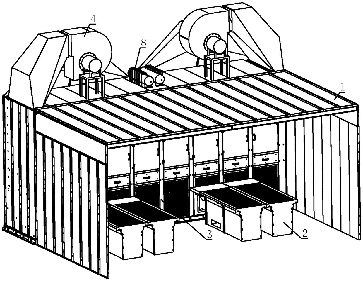
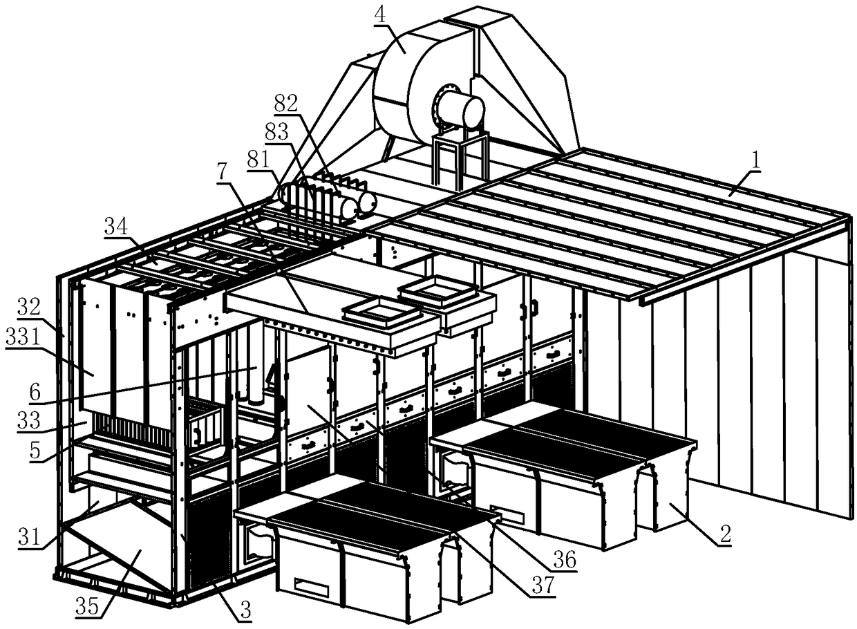
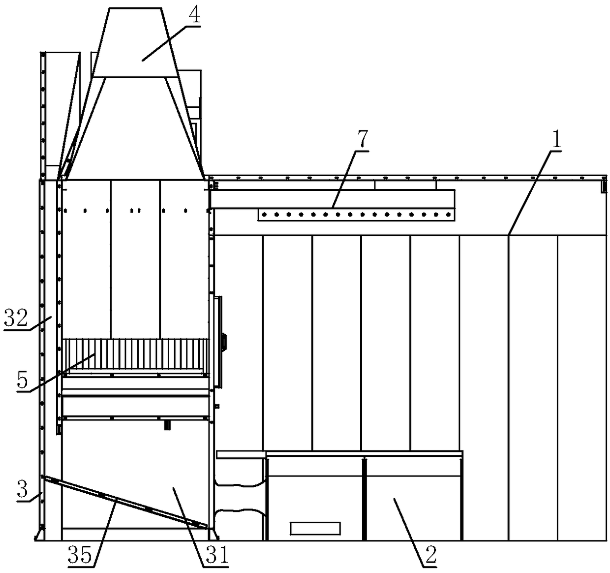
[0038] A grinding room with high dust removal rate, comprising a main body 1 of the grinding room, a grinding table 2 is installed in the main body 1 of the grinding room; a dust removal frame 3 is arranged in the main body 1 of the grinding room, and an air inlet cavity is arranged at the bottom of the dust removal frame 3 31, the air inlet cavity 31 is respectively connected with the interior of the main body of the grinding room 1 and the inner cavity of the grinding table 2, and the dust removal frame body 3 is also provided with an air inlet folder cavity 32, the air inlet cavity 31 communicates with the air inlet folder cavity 32, and the dust removal frame body 3 An exhaust fan 4 is installed on the top, and the air inlet of the exhaust fan 4 communicates with the air inlet folder chamber 32; a filter chamber 33 is arranged in the dust removal frame body 3, and the filter chamber 33 communicates with the air outlet of the exhaust fan 4, and the inside of the filter chambe...

Embodiment 2

[0043] On the basis of the first embodiment, a sloping plate 35 for partitioning and reducing the volume of the air inlet cavity is fixed inside the dust removal rack body 3 .

[0044] The setting of the sloping plate 35 further reduces the space size of the air inlet chamber 31, correspondingly increases the size of the negative pressure in the air inlet chamber 31, can further increase the inlet wind speed, and correspondingly improves the dust removal rate.

Embodiment 3

[0046] On the basis of Embodiment 1 or Embodiment 2, a dust collection drawer 36 is provided under the baffle plate 5 and the filter cloth bag 6 , and the dust collection drawer 36 is installed on the dust removal frame body 3 .

[0047] The dust falling on the baffle plate 5 and the filter cloth bag 6 can be collected by the dust collection drawer 36, so that when the exhaust fan 4 is closed, the dust collection drawer 36 can be opened to remove the dust, avoiding the need to disassemble the dust removal frame body 3 during the process. The trouble of removing dust in the wind chamber 31.


PUM


Abstract

The invention relates to the field of polishing rooms, in particular to a polishing room with a high dust removal rate. The polishing room with the high dust removal rate comprises a polishing room body. Polishing tables are mounted in the polishing room body. A dust removal frame is arranged in the polishing room body. An air inlet cavity is formed in the bottom of the dust removal frame. An airinlet interlayer cavity is formed in the dust removal frame. The air inlet cavity communicates with the air inlet interlayer cavity. An exhaust fan is mounted at the top of the dust removal frame. Anair inlet of the exhaust fan communicates with the air inlet interlayer cavity. A filter cavity is formed in the dust removal frame and communicates with an air outlet of the exhaust fan. Baffle plates and filter cloth bags are sequentially arranged in the filter cavity. A top air cavity is formed in the top of the dust removal frame. Openings of the filter cloth bags communicate with the top aircavity. An air outlet mechanism is mounted on the dust removal frame and communicates with the top air cavity. An air guide plate used for adjusting the air outlet direction is mounted on the air outlet mechanism. According to the polishing room, more dust can be sucked away, and thus, the dust removal rate is increased.

Description

technical field [0001] The invention relates to the field of grinding rooms, in particular to a grinding room with high dust removal rate. Background technique [0002] In the polishing workshop of the woodworking processing factory, the woodworking dust is very large, which seriously affects the health of the operators. In order to reduce the impact of dust on workers' bodies, the current common method is to use exhaust fans to pump the dust in the workshop to the outside. [0003] The utility model patent with the patent application number CN201520918702.8 discloses a pulse bag dry grinding room, which includes a grinding room body surrounded by hoardings, and the inside of the room body is the working area for grinding; One side inside the body is provided with a pulse bag filter, the pulse bag filter includes an air inlet on the side close to the working area, an air outlet on the upper part, an air duct is formed between the air inlet and the air outlet, A dust-removi...

Claims


Application Information

Patent Timeline
Patent Type & Authority Applications(China)
IPC IPC(8): B24B55/06B01D50/00
CPCB24B55/06B01D50/20
Inventor 李成雷富祥
Owner QUANYOU FURNITURE
Why Eureka
Try Eureka