Two-degree-of-freedom joint structure driven by three motors

A technology of joint structure and degrees of freedom, applied in the directions of manipulators, manufacturing tools, joints, etc., can solve problems such as affecting transmission accuracy, impact, and difficulty in eliminating transmission gaps.

Active Publication Date: 2018-12-21
NORTHEASTERN UNIV
View PDF11 Cites 10 Cited by
  • Summary
  • Abstract
  • Description
  • Claims
  • Application Information

AI Technical Summary

Problems solved by technology

[0005] The disadvantages of the above joint structure are: similar to the spur gear transmission, when the first bevel gear and the second bevel gear rotate forward in the same direction, the third bevel gear realizes the positive pitch degree of freedom, at this time the third bevel gear respectively One side of the first bevel gear and the second bevel gear is in close contact, and there is a transmission gap on the other side, so that an idle stroke is formed during reverse rotation, and impact occurs and affects transmission accuracy; when the first bevel gear and the second bevel gear When rotating in the reverse direction, the third bevel gear realizes the degree of freedom of rotation in the forward direction. At this time, the third bevel gear is in close contact with one side of the first bevel gear and the second bevel gear respectively, and there is a transmission gap on the other side, so that When reversing, an empty stroke is formed, and impact occurs and affects transmission accuracy
[0006] The shortcomings of the above-mentioned patents: the existing technology can achieve a good elimination effect on the transmission gap generated by one direction of motion. Once the reverse motion occurs, the transmission gap at this time is difficult to eliminate by the anti-backlash bevel gear that only provides rotation compensation torque

Method used


Image

  • Two-degree-of-freedom joint structure driven by three motors
  • Two-degree-of-freedom joint structure driven by three motors
  • Two-degree-of-freedom joint structure driven by three motors

Examples


Embodiment Construction

[0041] In order to better explain the present invention and facilitate understanding, the present invention will be described in detail below through specific embodiments in conjunction with the accompanying drawings.

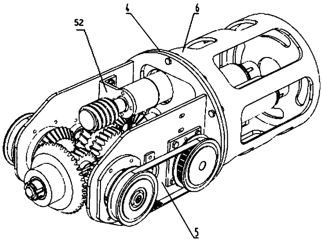
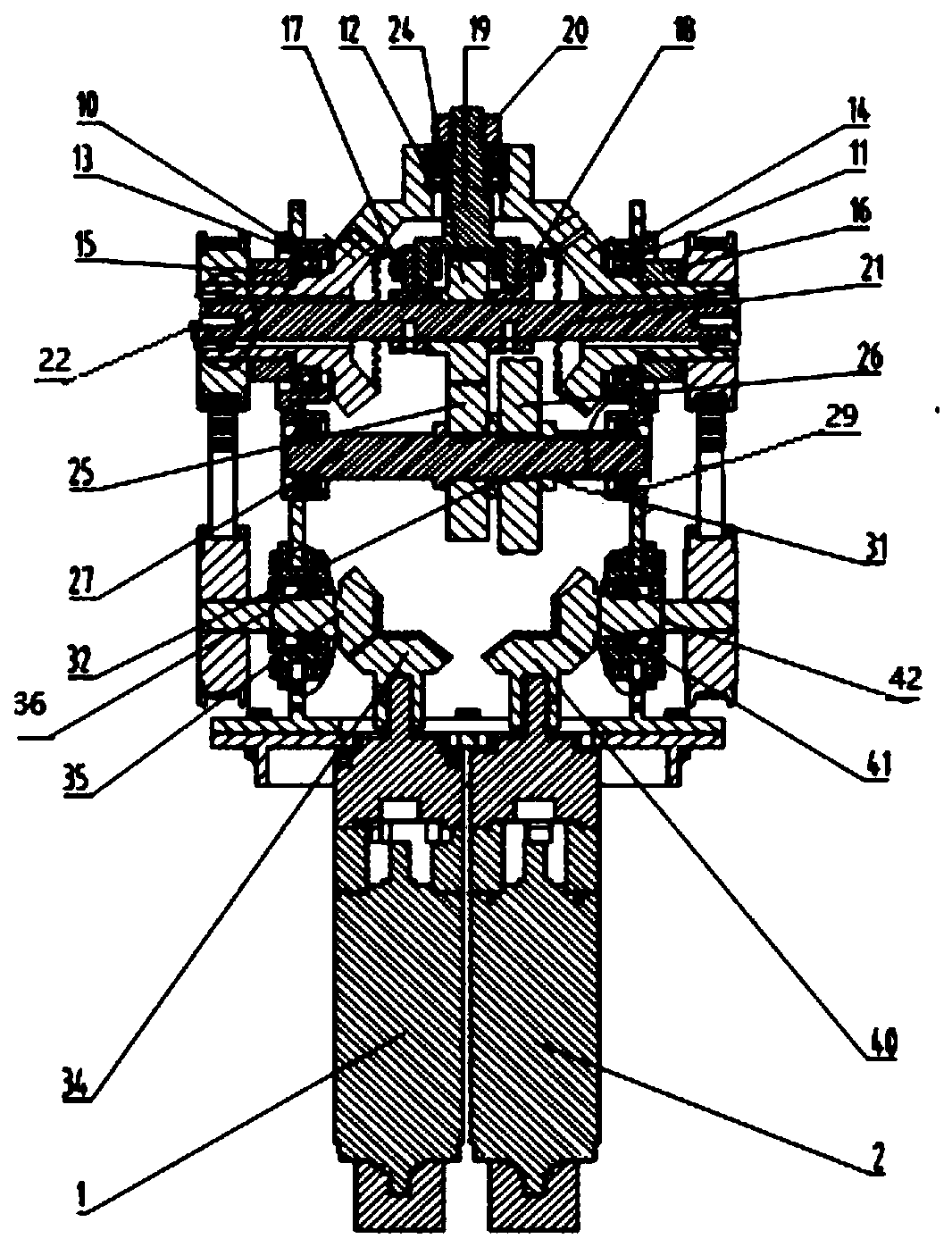
[0042] refer to Figure 1 ~ Figure 4 , A three-motor-driven two-degree-of-freedom joint structure provided by the present invention includes: a first transmission system, a second transmission system, an output system, a third transmission system, an intermediate connecting piece 4 , a frame 5 and a housing 6 .

[0043] first drive system

[0044] In the first transmission system, the first motor reducer 1 is fixedly connected to the intermediate connector 4 through screws, and the output shaft of the first motor reducer 1 is fixedly connected to the first transmission pinion bevel gear 34. Shaft connection, through set screw connection, etc. The first transmission large bevel gear 35 meshes with the first transmission small bevel gear 34 , and the former is ...


PUM


Abstract

The invention relates to a two-degree-of-freedom joint structure driven by three motors. The two-degree-of-freedom joint structure comprises a first motor reducer, a second motor reducer, a third motor reducer, a first transmission system, a second transmission system, a third transmission system, an output system, an intermediate connector, a rack and a housing, wherein the rack is connected withthe housing through the intermediate connector; the first motor reducer, the second motor reducer and the third motor reducer are mounted on the rack; the output system comprises a third supporting frame and an output bevel gear; the output bevel gear is connected with the third supporting frame in a sleeving manner; the first motor reducer drives, through the transmission of the first transmission system, the output bevel gear to rotate; the second motor reducer drives, through the transmission of the second transmission system, the output bevel gear to rotate; and the third motor reducer drives, through the transmission of the third transmission system, the third supporting frame to act. The two-degree-of-freedom joint structure can realize autoroatation and pitching motion and meanwhile eliminate the transmission return difference of reverse motion, thereby finally improving the transmission accuracy greatly.

Description

technical field [0001] The invention relates to the technical field of industrial robots, in particular to a two-degree-of-freedom joint structure driven by three motors. Background technique [0002] Robot technology is hailed as one of the greatest inventions of the 20th century. After decades of development, industrial robots have become an indispensable core equipment in the manufacturing industry. complete a specific function. The joint structure is the core functional part of an industrial robot. The difference in the structure of this part is directly related to the working space range and transmission accuracy of the robot itself. At present, the joint structures of common industrial robots are generally single-degree-of-freedom or two-degree-of-freedom. [0003] A joint structure in the prior art includes a first bevel gear, a second bevel gear and a third bevel gear, and the first bevel gear and the second bevel gear mesh with the third bevel gear at the same tim...

Claims


Application Information

Patent Timeline
Patent Type & Authority Applications(China)
IPC IPC(8): B25J17/02
CPCB25J17/0266
Inventor 房立金徐妍
Owner NORTHEASTERN UNIV
Why Eureka
Try Eureka