Oil-gas separator filter element cutting device

A technology of oil-gas separator and filter element, which is applied in the direction of metal processing, etc., can solve the problems of low cutting efficiency, low use reliability, and poor fixing effect of filter materials, so as to improve cutting work efficiency, improve use reliability, Improving the effect of fixed effects

Inactive Publication Date: 2018-12-21
诺贝特空调(盐城)有限公司
View PDF0 Cites 8 Cited by
  • Summary
  • Abstract
  • Description
  • Claims
  • Application Information

AI Technical Summary

Problems solved by technology

[0002] As we all know, the filter element of the oil-gas separator is a device that separates the gas in the lubricating oil to ensure the normal operation of the lubrication system. The filter element of the oil-gas separator includes a shell and a filter material. Then install it inside the shell. The oil-gas separator filter element cutting device is an auxiliary device used for cutting and processing the filter material during the production and processing of the oil-gas separator. It is used in the production of automotive air compressor accessories. It has been widely used in the field; the existing oil-gas separator filter element cutting device includes a cutting table, a cutting support is arranged on the cutting table, and a cutting cylinder is arranged on the cutting support, and a piston rod is provided at the bottom output end of the cutting cylinder. , the bottom end of the piston rod passes through the bottom of the cutting

Method used


Image

  • Oil-gas separator filter element cutting device
  • Oil-gas separator filter element cutting device
  • Oil-gas separator filter element cutting device

Examples


Example Embodiment

[0021] The specific embodiments of the present invention will be described in further detail below in conjunction with the drawings and embodiments. The following examples are used to illustrate the present invention, but not to limit the scope of the present invention.
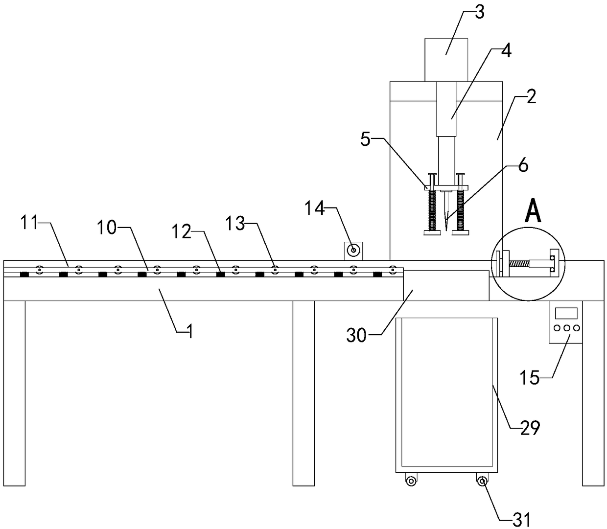
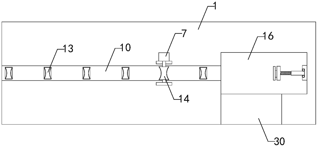
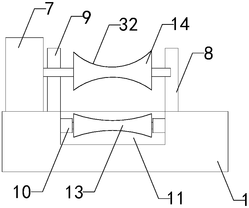
[0022] Such as Figure 1 to Figure 7 As shown, an oil-air separator filter element cutting device of the present invention includes a cutting table 1, a cutting support 2 is provided on the cutting table, and a cutting cylinder 3 is provided on the cutting support, and the bottom output end of the cutting cylinder is provided with a piston Rod 4, the bottom end of the piston rod passes under the cutting support from the top end of the cutting support, and a mounting plate 5 is provided at the bottom end of the piston rod, and a cutter 6 is provided at the bottom end of the mounting plate; it also includes a drive motor 7, a front The supporting plate 8, the rear supporting plate 9 and the conveying plate 10, th...


PUM

PropertyMeasurementUnit
Elastic coefficientaaaaaaaaaa

Abstract

The invention relates to the technical field of oil-gas separator production and machining accessory devices, in particular to an oil-gas separator filter element cutting device. A filter material fixing effect is improved, the cutting accuracy is guaranteed, and the practicability is enhanced; and moreover, the potential safety hazard is reduced and the reliability in use is enhanced; and meanwhile, the filter material can be rapidly positioned so that the cutting efficiency is enhanced. The oil-gas separator filter element cutting device comprises a cutting platform, a cutting bracket, a cutting cylinder, a piston rod, a mounting plate, a cutting knife, a driving motor, a front supporting plate, a rear supporting plate and a conveying plate; a transverse conveying groove is formed in thetop end of the cutting platform; the conveying plate is positioned in the conveying groove; multiple groups of supporting springs are arranged at the bottom end of the conveying plate; multiple groups of conveying wheels are arranged on the conveying plate in an unequally-spaced manner; a driving wheel is arranged between the front supporting plate and the rear supporting plate; the oil-gas separator filter element cutting device further comprises a positioning device and a controller; a cutting groove is formed in the top end of the cutting platform; and the positioning device comprises a fixing plate, a threaded rod, a threaded tube, a supporting plate, a push plate, a pressure sensor and a ball bearing.

Description

technical field [0001] The invention relates to the technical field of production and processing accessories of an oil-gas separator, in particular to a cutting device for a filter element of an oil-gas separator. Background technique [0002] As we all know, the filter element of the oil-gas separator is a device that separates the gas in the lubricating oil to ensure the normal operation of the lubrication system. The filter element of the oil-gas separator includes a shell and a filter material. Then install it inside the shell. The oil-gas separator filter element cutting device is an auxiliary device used for cutting and processing the filter material during the production and processing of the oil-gas separator. It is used in the production of automotive air compressor accessories. It has been widely used in the field; the existing oil-gas separator filter element cutting device includes a cutting table, a cutting support is arranged on the cutting table, and a cutting...

Claims


Application Information

Patent Timeline
IPC IPC(8): B26D1/08B26D5/12B26D5/28B26D7/02B26D7/06B26D7/28B26D7/32
CPCB26D1/08B26D5/12B26D5/28B26D7/02B26D7/06B26D7/28B26D7/32
Inventor 孙建华桑晨阳
Owner 诺贝特空调(盐城)有限公司
Why Eureka
Try Eureka