Pure electric vehicle and powertrain system

A technology for powertrains and automobiles, applied in the direction of electric power units, power units, vehicle components, etc., can solve the problems of poor use effect, increased motor volume, increased cost, etc., to simplify assembly and positioning relationships, and avoid reliability Low, the effect of improving reliability

Pending Publication Date: 2018-12-21
GUANGZHOU AUTOMOBILE GROUP CO LTD
View PDF0 Cites 1 Cited by
  • Summary
  • Abstract
  • Description
  • Claims
  • Application Information

AI Technical Summary

Problems solved by technology

The transmission work of the powertrain system of a traditional pure electric vehicle is generally realized through a parallel offset two-stage involute helical gear structure with a fixed speed ratio. With this structure, if a larger wheel end torque output is required , it is necessary to increase the torque output of the motor or increase the transmission ratio, but increasing the torque output of the motor will increase the volume of the motor, thereby increasing the cost; and increasing the transmission ratio will require the overall layout of the transmission structure of the powert...

Method used


Image

  • Pure electric vehicle and powertrain system
  • Pure electric vehicle and powertrain system
  • Pure electric vehicle and powertrain system

Examples


Embodiment 1

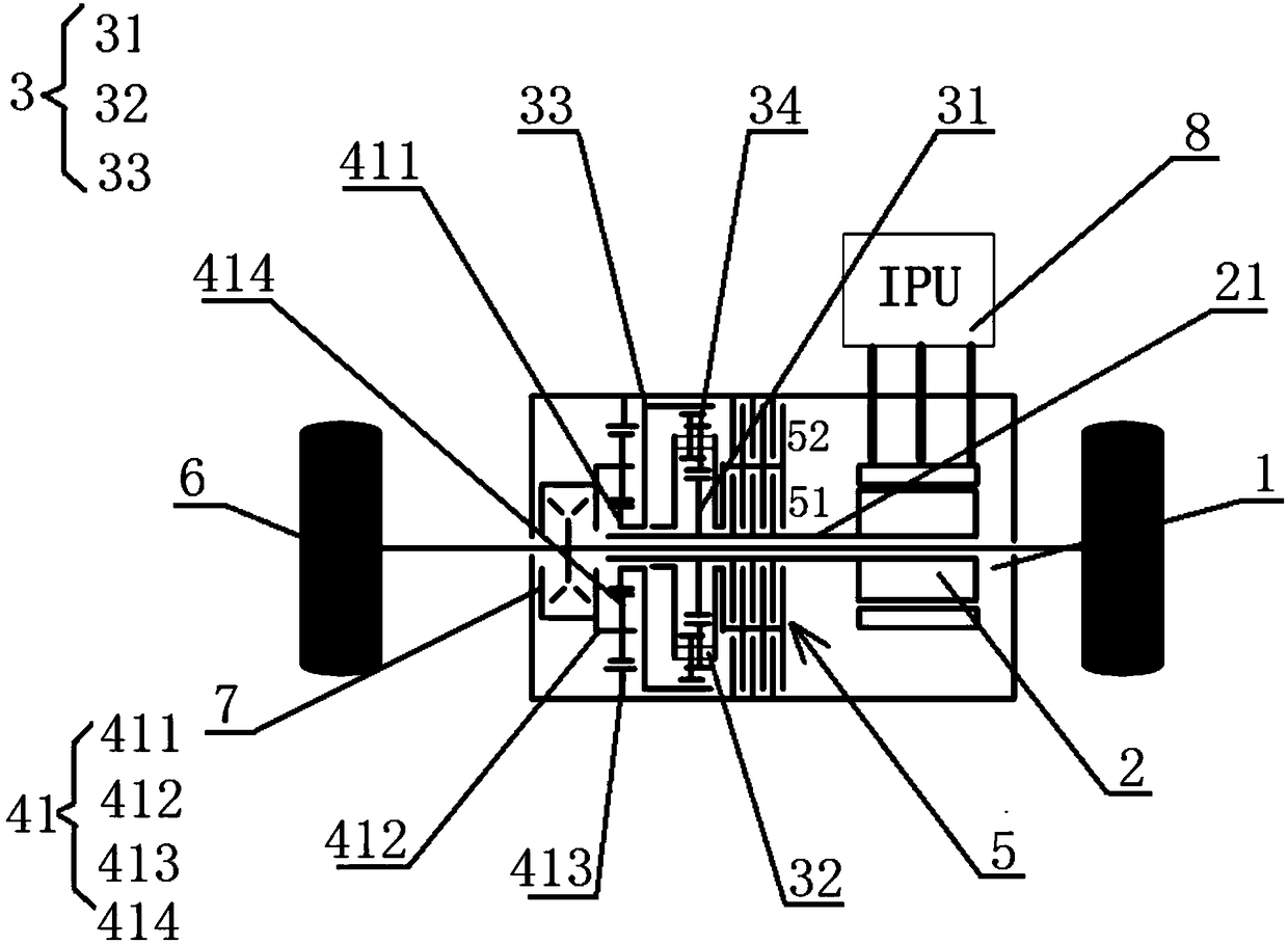
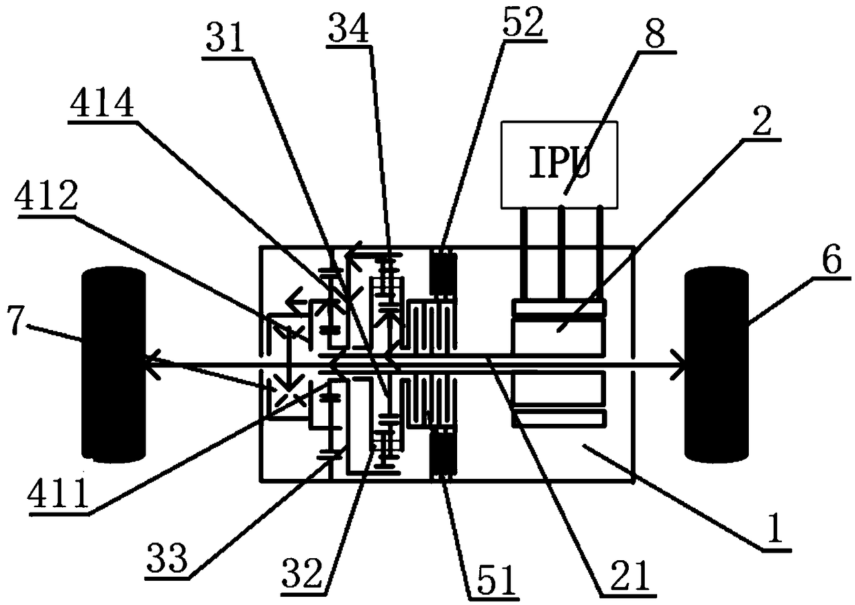
[0031] See Figure 1 to Figure 3 , The powertrain system of this preferred embodiment includes a housing 1, an electric motor 2, a first planetary row 3, a speed change mechanism 4 and a control shift device 5; the control shift device 5 is connected to the output shaft 21 of the motor and controls The shifting device 5 is connected to the housing 1, and the first planetary row 3 is connected between the control shifting device 5 and the speed change mechanism 4; the first planetary row 3 includes three first rotating elements, and the three first rotating elements are respectively The first sun gear 31, the first planet carrier 32, and the first ring gear 33; one of the three first rotating elements is connected to the housing 1, through the control shift device 5 The output shaft 21 of the electric motor is connected, and the control shift device 5 selectively works to realize the braking or rotation of the first rotating element connected with the output shaft 21 of the elec...

Embodiment 2

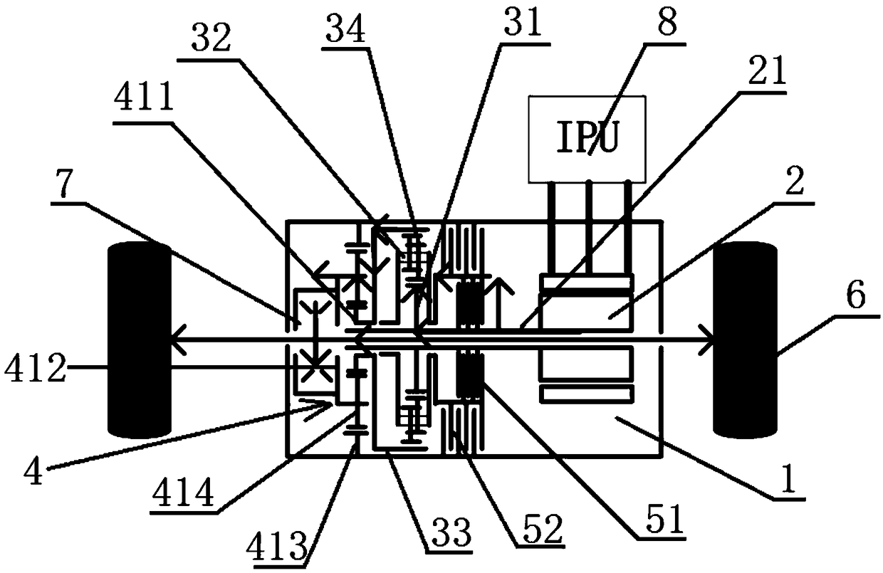
[0039] See Figure 4 The structural layout of the powertrain system in this preferred embodiment is substantially the same as that in the first embodiment, except that the speed change mechanism 4 includes a first gear device 42, a rotating shaft 43, and a second gear device 44. The first gear The device 42 is connected to the second gear device 44 through the shaft 43, the first gear device 42 is connected to the first ring gear 33, and the second gear device 44 is connected to the wheel end 6 of the automobile. The first gear device 42 includes a first gear device. The driving gear and the first driven gear. The second gear device 44 includes a second driving gear and a second driven gear. The power of the first planetary row 3 is transmitted through the first ring gear 33. A driving gear is connected to drive the first driving gear to rotate. The first driving gear and the first driven gear are meshed with each other. Power is transmitted from the first driven gear. The first...


PUM


Abstract

The invention provides a pure electric vehicle and a powertrain system, comprising a housing, an electric motor, a first planetary row, a transmission mechanism and a control shifting device. A firstplanetary row includes three first rotating elements, one of the three first rotating elements controls the shifting device and the housing, the output shaft of the motor is connected to control the selective operation of the shifting device so as to realize braking or rotation, and the other two of the three first rotating elements are respectively connected with the output shaft of the motor andthe input ends of the transmission mechanism one by one; The output end of the transmission mechanism is used for driving and connecting to the wheel end of the automobile. The transmission mechanismhas a two-step ratio of less than 2, so that the torque demand of the motor can be reduced and the output torque of the wheel end of the automobile can be increased, and the ride comfort of the vehicle can be ensured; moreover, the whole structure of the transmission mechanism is compact, the integration level is high, the control is simple and the cost is low.

Description

Technical field [0001] The present invention relates to the field of automobile technology, in particular to a pure electric automobile and a powertrain system. Background technique [0002] With the increasing awareness of environmental protection, the development and utilization of new energy has become more and more important and popular. As an important part of environmental protection, the automotive industry needs to design and develop new energy pure electric vehicles in accordance with the times. What comes is the change and update of the transmission system of new energy pure electric vehicles. The transmission work of the powertrain system of traditional pure electric vehicles is generally realized by a parallel-offset two-stage involute helical gear structure with a fixed speed ratio. With this structure, if a larger wheel-end torque output is required, , It is necessary to increase the torque output of the motor or increase the transmission ratio, but increasing the ...

Claims


Application Information

Patent Timeline
IPC IPC(8): B60K1/00B60K17/04B60K17/16
CPCB60K1/00B60K17/046B60K17/16
Inventor 尚阳赵江灵喻皓祖国强任晓华毋存祥
Owner GUANGZHOU AUTOMOBILE GROUP CO LTD
Why Eureka
Try Eureka