
Equipment for bombarding surface of workpiece through energetic plasma and forming smooth plating layer
A plasma and workpiece surface technology, applied in the direction of ion implantation plating, coating, sputtering plating, etc., can solve the problem of low utilization rate of target materials, and achieve the effect of ensuring quality, uniform coating and avoiding waste.
Patent Information
- Authority / Receiving Office
- CN · China
- Patent Type
- Applications(China)
- Current Assignee / Owner
- Publication Date
- 2018-12-21
Smart Images
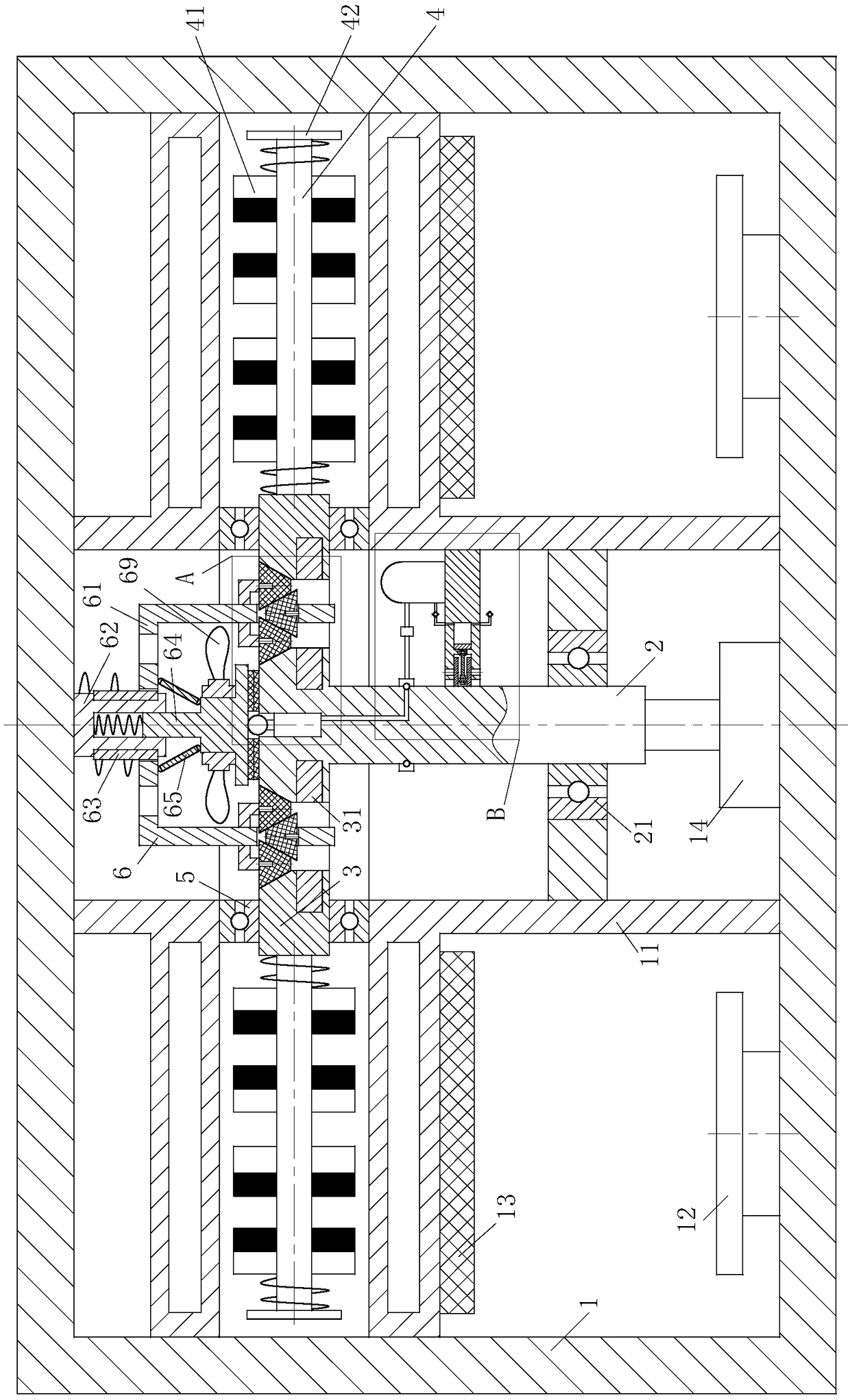
Figure 1 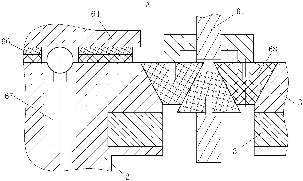
Figure 2 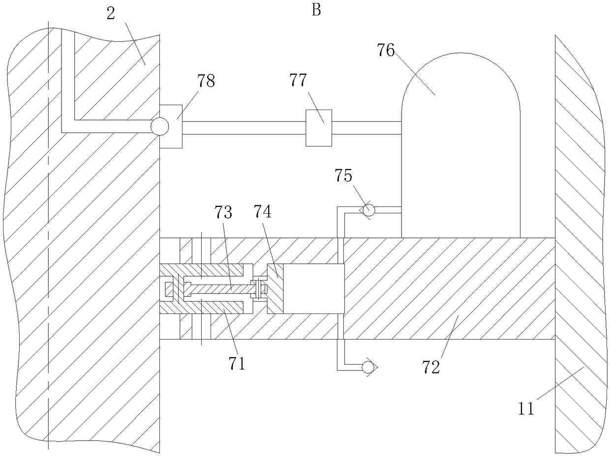
Figure 3
Abstract
Description
technical field
[0001] The invention belongs to the technical field of coating, in particular to a device which uses high-energy plasma to bombard the surface of a workpiece and forms a smooth coating. Background technique
[0002] Sputtering is a physical vapor deposition technology. The principle of sputtering is to use high-energy plasma generated by glow discharge or ion beam to hit the target material in a vacuum environment, and bombard the atoms in the target material from the target material by means of momentum transfer. out and deposited on the substrate to form a thin film. Because sputtering can achieve better deposition efficiency, precise composition control, and lower manufacturing costs, it has been widely used in the production of various metal and non-metal films in industry.
[0003] A cylindrical magnetron sputtering device generally includes a cylindrical shell, a cylindrical target placed in the cylindrical shell, and a magnet group placed in the cylin...
Examples
Embodiment Construction
[0021] In order to make the technical means, creative features, goals and effects achieved by the present invention easy to understand, the present invention will be further described below in conjunction with specific embodiments.
[0022] Such as Figure 1 to Figure 3 As shown, a device that uses high-energy plasma to bombard the surface of a workpiece and forms a smooth coating according to the present invention includes an outer shell 1, an inner shell 11, a workbench 12, a target 13, a motor 14, a rotating shaft 2, a No. bearing 21, the inner shell 11 divides the outer shell 1 into a sputtering space and an accommodating space; the target 13 is fixedly connected to the top of the sputtering space, and a workbench 12 is arranged below the target 13; The workbench 12 is fixedly connected to the bottom plate of the outer casing 1; the rotating shaft 2 is arranged in the accommodation space, the lower end of the rotating shaft 2 is fixedly connected to the shaft end of the mo...