External cast-in-situ heat preservation wall and construction method thereof

A construction method and external thermal insulation technology, applied in thermal insulation, building components, buildings, etc., can solve problems such as affecting the service life of the thermal insulation layer, easy falling off and failure of thermal insulation boards, etc. Effect

Inactive Publication Date: 2018-12-21
四川恒达兴铁科技有限公司
View PDF0 Cites 3 Cited by
  • Summary
  • Abstract
  • Description
  • Claims
  • Application Information

AI Technical Summary

Problems solved by technology

[0005] The purpose of the present invention is to: install the thermal insulation layer of the existing building wall by pasting or anchor bolt connection, and do not deal with the splicing gap of the thermal insulation board, which will cause the thermal insulation board to fall off easily and fail, and affect the service life of the thermal insulation layer. problem, to provide a cast-in-place external thermal insulation wall and its construction method that is stable in installation and not easy to immerse in rainwater or air in the gap

Method used


Image

  • External cast-in-situ heat preservation wall and construction method thereof
  • External cast-in-situ heat preservation wall and construction method thereof
  • External cast-in-situ heat preservation wall and construction method thereof

Examples


Embodiment 1

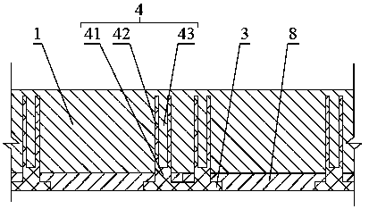
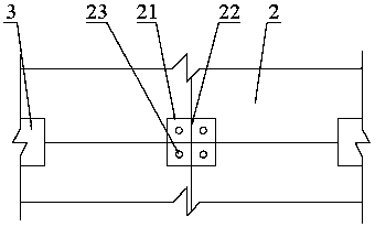
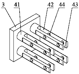
[0037] like Figure 1-5As shown, a cast-in-place external thermal insulation wall includes a wall 1 and several rectangular thermal insulation boards 2 arranged on the surface of the wall 1. The outer edge of each thermal insulation board 2 is provided with a step 21 that runs through the edge of the thermal insulation board 2. A groove is formed after the adjacent insulation boards 2 are in contact, and the splicing gap 22 between the adjacent insulation boards 2 is located in the groove, and a connecting plate 3 adapted to the groove is also included, and on the connecting plate 3 Several connecting pieces 4 are provided, one end of the connecting piece 4 is fixedly connected with the connecting plate 3 , and the other end extends into the wall body 1 after passing through the bottom of the groove.

[0038] A cast-in-place external thermal insulation wall of this embodiment, by setting steps 21 on the thermal insulation board 2, the thermal insulation board 2 is spliced ​​to...

Embodiment 2

[0043] like Figure 1-5 As shown, a cast-in-place external thermal insulation wall of this embodiment has the same structure as that of Embodiment 1, the difference is that the number of the reinforcement boards 42 is at least two, and the reinforcement boards 42 are formed between two adjacent reinforcement boards The gap 43 through which the concrete slurry passes.

[0044] A kind of cast-in-place external thermal insulation wall body of this embodiment preferably arranges two reinforcing plates 42 of plate-like structure on the same connecting column 41. The height directions are parallel, so that the two reinforcing plates 42 extend into the wall 1 at the same time, and are fixed by the concrete slurry, so that the connection between the connecting plate 3 and the wall 1 is more stable, so that the setting of the insulation board 2 is more stable. The service life of the cast-in-place external thermal insulation wall of this structure is further extended. At the same time...

Embodiment 3

[0048] like Figure 1-5 As shown, a cast-in-place external thermal insulation wall of this embodiment has the same structure as that of Embodiment 1, the difference is that several reinforcing columns 5 are arranged inside the wall 1, and the reinforcing columns 5 are arranged along the splicing gap. 22 settings.

[0049] A cast-in-place external thermal insulation wall in this embodiment is provided with reinforcing columns 5 along the splicing gap 22 in the wall 1, on the one hand, the splicing gap between the thermal insulation boards 2 is fixed from the inner side of the wall 1 through the reinforcing columns 5 22 to carry out sealing treatment to prevent the moisture in the concrete slurry from entering the gap and affect the overall thermal insulation effect of the thermal insulation layer 8. At the same time, it is also beneficial to increase the overall strength of the thermal insulation layer 8 through the setting of the reinforcing column 5, so as to prevent the ther...


PUM


Abstract

The invention relates to heat preservation structures for building walls, in particular to an external cast-in-situ heat preservation wall and a construction method thereof. The external cast-in-situheat preservation wall comprises a wall body and multiple rectangular heat preservation plates arranged on the surface of the wall body, steps penetrating through the edges of the heat preservation plates are arranged at the edges of the outer sides of all the heat preservation plates, and accordingly every two adjacent heat preservation plates are in contact to form a groove; a spliced gap between every two adjacent heat preservation plates is located in the corresponding groove, the wall further comprises connection plates matched with the grooves, multiple connectors are arranged on the connection plates, one end of each connector is fixedly connected with the corresponding connection plate, and the other end of each connector penetrates through the bottom of the corresponding groove and then extends into the wall body, so that the connectors are fixed in the wall body formed through pouring. The heat preservation plates are stably limited on the surface of the wall body through theconnection plates, so that the heat preservation plates are stably installed, do not easily fall off and are not easily damaged; the spliced gap between every two adjacent heat preservation plates isclosed inside, so that the service life of the heat preservation plates is long, few construction steps of the external cast-in-situ heat preservation wall are needed, and operation is easy.

Description

technical field [0001] The invention relates to a building wall thermal insulation structure, in particular to a cast-in-place external thermal insulation wall and a construction method thereof. Background technique [0002] Adding an insulation layer on the wall of the building is beneficial to avoid the mutual diffusion of heat inside and outside the wall, avoiding the occurrence of cold and heat bridges in the weak parts of the building's outer wall envelope, and effectively reducing the energy consumption of air conditioners. At present, in buildings It has become an important measure for energy saving and emission reduction to set insulation layer on the wall body of buildings. [0003] The existing insulation layer is generally installed by pasting or anchor bolt connection. The insulation layer using the pasting method is affected by the flatness of the wall surface, and a virtual connection structure is likely to appear between the wall surface and the insulation lay...

Claims


Application Information

Patent Timeline
Patent Type & Authority Applications(China)
IPC IPC(8): E04B1/76
CPCE04B1/762E04B1/7629
Inventor 李红梅
Owner 四川恒达兴铁科技有限公司
Why Eureka
Try Eureka