Workbench flatness detection device

A detection device and flatness technology, applied in the direction of mechanical roughness/irregularity measurement, etc., can solve the problems of inability to adapt to the mass production requirements of CNC center workbenches, low detection accuracy, low work efficiency, etc. High efficiency and improved level effect

Inactive Publication Date: 2018-12-21
安徽省临泉县智创精机有限公司
View PDF2 Cites 8 Cited by
  • Summary
  • Abstract
  • Description
  • Claims
  • Application Information

AI Technical Summary

Problems solved by technology

[0002] The flatness of the working surface of the workbench is the main precision index to measure the quality of the workbench. The detection of the flatness of the existing CNC center worktable is generally carried out manually by using a level instrument or an adjustable bridge plate for flatness detection, and the detection accuracy is low. The operation is cumbersome and the work efficiency is low, which can no longer meet the mass production requirements of the CNC center workbench with high flatness requirements

Method used


Image

  • Workbench flatness detection device
  • Workbench flatness detection device
  • Workbench flatness detection device

Examples


Embodiment Construction

[0024] Through the description of the embodiments below, the specific implementation of the present invention includes the shape, structure, mutual position and connection relationship between the various parts, the function and working principle of each part, the manufacturing process and the operation and use method of the various components involved. etc., to make further detailed descriptions to help those skilled in the art have a more complete, accurate and in-depth understanding of the inventive concepts and technical solutions of the present invention. ", "Bottom", "Front", "Back", "Left", "Right", "Inner", "Outer", "Side", etc., are only for reference to the direction and position of the attached drawing, therefore, the used The terms of direction and position are used to illustrate and understand the present invention, but not to limit the present invention.

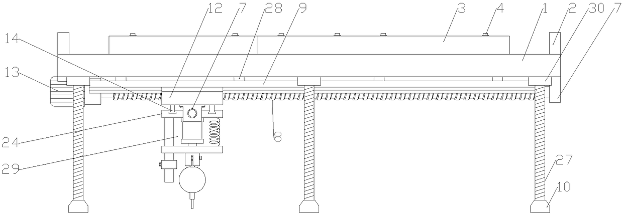
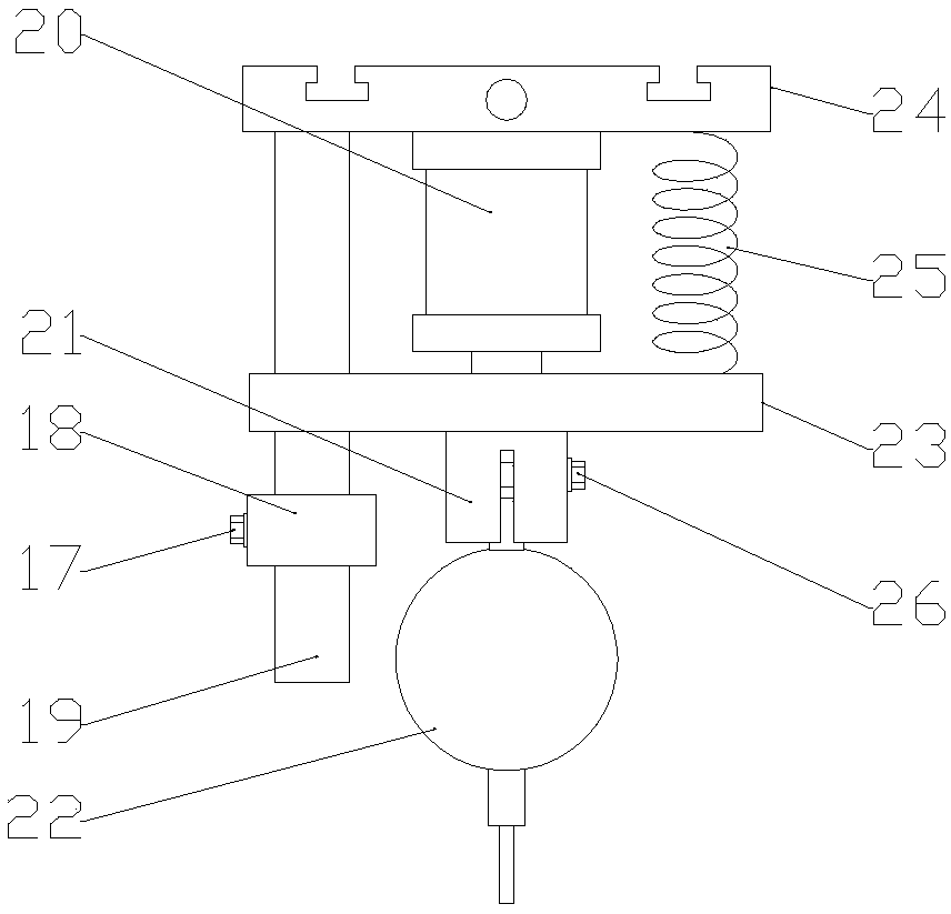
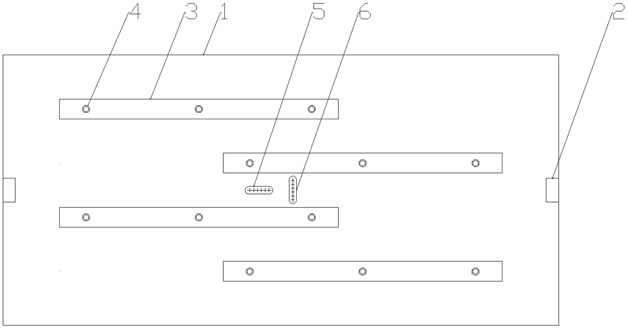
[0025] Figure 1-6 A workbench flatness detection device is shown, including a flat plate 1, a horizontal t...


PUM


Abstract

The invention discloses a workbench flatness detection device, comprising a flat plate, a horizontal pipe I and a horizontal pipe II which are vertical to each other are arranged at the middle part ofthe upper end of the flat plate, screws connected by virtue of a screw thread are arranged at four corners of the lower end of the flat plate and midpoints of long sides, a gear motor I and a bearingblock I are fixed at the lower ends of the two sides of the flat plate, a lead screw I is arranged at the output terminal of the gear motor I, the lead screw I is coincided with a symmetric axis in the length direction of the flat plate, sliding rails I are arranged at the two sides of the lead screw I in parallel, a strut is arranged at the upper end of each sliding rail I, the struts are fixedon the lower end face of the flat plate, the lead screw I is provided with a movable plate I connected by virtue of a screw thread, a gear motor II and a bearing block II are respectively fixed at thetwo ends of the movable plate I, a lead screw II is arranged at the output terminal of the gear motor II, a movable plate II connected by virtue of a screw thread is arranged on the lead screw II, and a detector is arranged at the lower end of the movable plate II. The workbench flatness detection device disclosed by the invention controls movement of the detection device in the horizontal direction by utilizing the gear motor I and the gear motor II, flatness is detected by virtue of a dial gauge, an operation method is simple, and detection precision is high.

Description

technical field [0001] The invention belongs to the technical field of numerical control centers, and in particular relates to a workbench flatness detection device. Background technique [0002] The flatness of the working surface of the workbench is the main precision index to measure the quality of the workbench. The detection of the flatness of the existing CNC center worktable is generally carried out manually by using a level instrument or an adjustable bridge plate for flatness detection, and the detection accuracy is low. The operation is cumbersome and the work efficiency is low, which can no longer meet the mass production requirements of the CNC center workbench with higher flatness requirements. Contents of the invention [0003] According to the deficiencies of the prior art above, the technical problem to be solved by the present invention is to provide a workbench flatness detection device to solve the above-mentioned multiple defects caused by the prior art...

Claims


Application Information

Patent Timeline
Patent Type & Authority Applications(China)
IPC IPC(8): G01B5/28
CPCG01B5/28
Inventor 孙涛赵峰王子彬张玲牛敬仁潘克福
Owner 安徽省临泉县智创精机有限公司
Why Eureka
Try Eureka