
Contractible array device for testing substation noise cloud picture and the operating method

A technology for testing devices and substations, applied to measuring devices, measuring ultrasonic/sonic/infrasonic waves, instruments, etc., can solve problems such as high test cost, troublesome operation, stop running, etc., and achieve reduced test cost, high test efficiency, and enhanced stability sexual effect

Inactive Publication Date: 2018-12-21
XIAN POWER TRANSMISSION & TRANSFORMATION PROJECT ENVIRONMENTAL IMPACT CONTROL TECHN CENT CO LTD +2
View PDF4 Cites 0 Cited by
  • Summary
  • Abstract
  • Description
  • Claims
  • Application Information

AI Technical Summary

Problems solved by technology

However, the substation in operation cannot be stopped just because of the measurement of its environmental noise, so the noise measured by a single sound level meter is the superposition of the substation's own noise and other environmental noise
Using a single sound level meter, it is difficult to distinguish the source, distribution, size, spectrum characteristics and other parameters of the internal noise of the substation, which is not conducive to the division of responsibilities for substation equipment noise, and brings inconvenience to the control of substation environmental noise
[0003] At present, the sound field distribution map in the substation can be obtained more accurately by using the volume array noise test device, but the existing volume array test device cannot be contracted, and the transportation is difficult; using it for noise test operation is cumbersome and the efficiency is low; It needs to be disassembled and assembled every time it is used, which takes a long time and is easy to damage the components, especially the thin-film acoustic sensor is a fragile component, the cost of the sensor accounts for about 20% of the overall cost, and the test cost is relatively high

Method used


Image

  • Contractible array device for testing substation noise cloud picture and the operating method
  • Contractible array device for testing substation noise cloud picture and the operating method
  • Contractible array device for testing substation noise cloud picture and the operating method

Examples


Embodiment Construction

[0040] The present invention will be described in further detail below in conjunction with the accompanying drawings and specific embodiments.

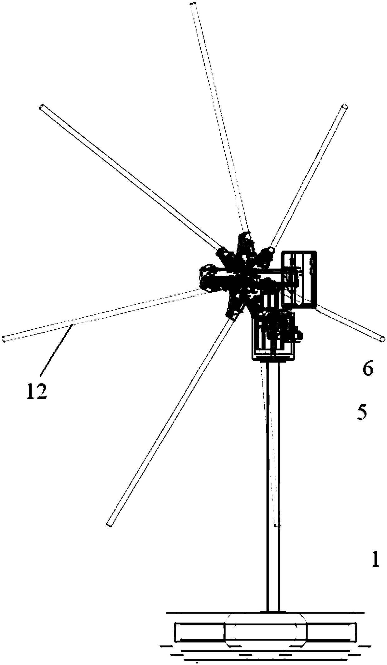
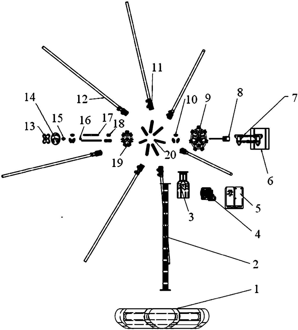
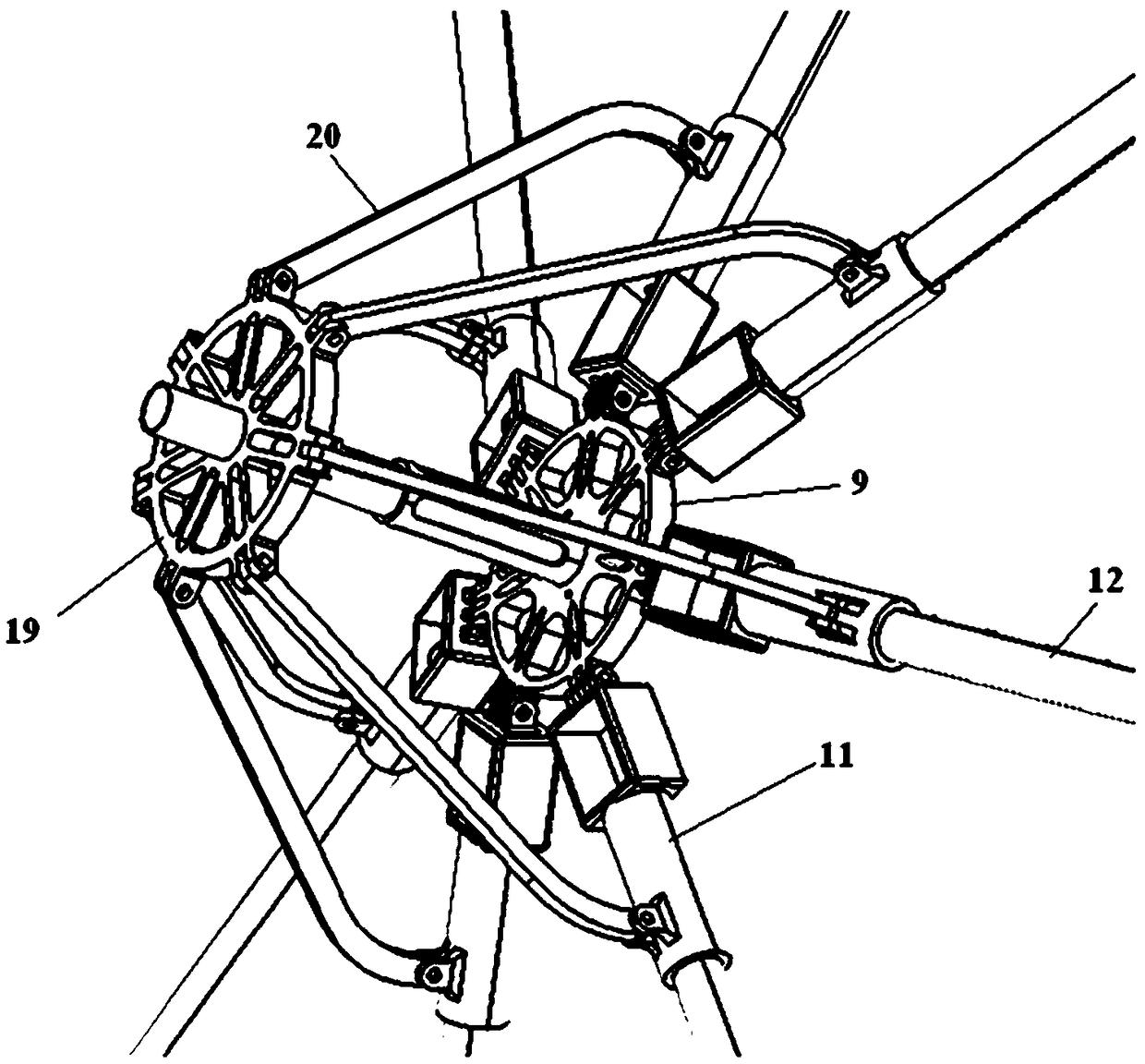
[0041] refer to Figure 1 to Figure 3, a shrinkable volume array substation noise nephogram test device of the present invention, including: a support frame, a fixed plate 9, a floating plate 19, a pitch adjustment device, a control box 6 and several array arms 12.

[0042] The pitch adjustment device includes a pitch adjustment motor 4 and a rotating arm 3, the pitch adjustment motor 4 is fixedly installed on the support frame, the output shaft of the pitch adjustment motor 4 is connected with the rotating arm 3 through a transmission device, and the fixed plate 9 is fixedly installed by a fixed arm 7 On the rotating arm 3 , the pitch adjustment motor 4 drives the rotating arm 3 to drive the fixed disk 9 to rotate, which can realize the adjustment of the angle measurement in the vertical direction of the array arm 12 . The current t...


PUM


Abstract

The invention discloses a contractible array device for testing substation noise cloud picture and the operating method. The device comprises a support frame, a fixing disk, a floating disk, and a plurality of array arms. The fixing disk is mounted on the support frame and is provided with camera and tracks, on which the floating disk is installed. Each array arm is hinged on the fixed disk and isconnected to the floating disk through a connecting rod. One end of a connecting rod is hinged on the array arm and another end on the floating disk. Meanwhile, each array arm is provided with a plurality of acoustic sensors. The outputs from the camera and each acoustic sensor are all connected to the data acquisition, processing and transmission device. The invented array device is contractibleto reduce volume for convenient transportation. It is also convenient in operation and efficient in acquiring sound field distribution map. In addition it is featured by no need to reassemble beforeuse, longevity and lower test cost.

Description

technical field [0001] The invention belongs to the technical field of substation noise testing, in particular to a shrinkable volume array type substation noise cloud image testing device and an operation method thereof. Background technique [0002] Accurate separation and measurement of substation internal noise is the key to the control and prevention of substation environmental noise. However, the measurement of substation noise is affected by external environmental factors, including background noise and weather. In the actual measurement, in addition to the noise generated by the sound source under test, there will also be other noises, such as the impact of noise from living and working backgrounds such as the flow of people and traffic around the substation, as well as transient noises such as dog barking and motorcycle sound. Noise, the sum of these noises is called background noise, background noise will affect the accuracy of the measurement. Usually the noise ...

Claims


Application Information

Patent Timeline
Patent Type & Authority Applications(China)
IPC IPC(8): G01H17/00
CPCG01H17/00
Inventor 申晨刘志远郭微白晓春王绿杨彬丁德申秦荣陈勃吴子豪
Owner XIAN POWER TRANSMISSION & TRANSFORMATION PROJECT ENVIRONMENTAL IMPACT CONTROL TECHN CENT CO LTD
Learn More