Atomic force microscope probe device

A technology of atomic force microscope and probe, which is applied in the direction of measuring device, scanning probe technology, scanning probe microscopy, etc., to achieve the effect of improving the success rate, improving the test effect and promoting the sensitivity

Active Publication Date: 2018-12-21
HENAN UNIVERSITY
View PDF11 Cites 4 Cited by
  • Summary
  • Abstract
  • Description
  • Claims
  • Application Information

AI Technical Summary

Problems solved by technology

In the prior art, there is no attention and research on the influence of the tightness of the end of the AFM probe on the test effect

Method used


Image

  • Atomic force microscope probe device
  • Atomic force microscope probe device
  • Atomic force microscope probe device

Examples


Embodiment Construction

[0017] In order to make the content of the present invention clearer and easier to understand, the content of the present invention will be further described below in conjunction with the accompanying drawings. Of course, the present invention is not limited to this specific embodiment, and general replacements known to those skilled in the art are also covered within the protection scope of the present invention.

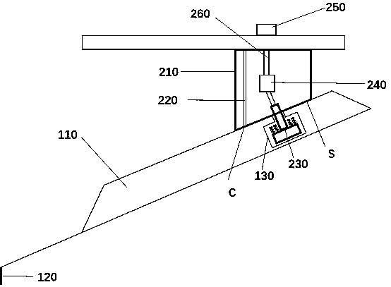
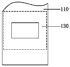
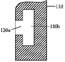
[0018] Please refer to Figure 1 to Figure 4 , the atomic force microscope probe device provided in this embodiment includes a probe pin and a probe base. The probe includes a micro-cantilever 110 fixed on the probe base and a needle tip 120 arranged at one end of the micro-cantilever. The surface of the microcantilever 110 on which the needle tip 120 is placed is taken as the front side, and the surface opposite to the needle tip 120 is called the back side. In this embodiment, the microcantilever 110 is fixed in the probe holder by vacuum adsorption. Specifica...


PUM


Abstract

The invention discloses a combination device of an atomic force microscope probe and a base, wherein a step hole is formed in the surface, opposite to a needle point, of a micro-cantilever of the probe; a probe base comprises an adsorption part and a positioning part, wherein the adsorption part comprises a vacuum adsorption groove and an adsorption surface; the positioning part extends out of theadsorption surface and is inserted into the step hole and is rotated to abut against the stepped surface of the step hole; the positioning part comprises a rotating rod and a rotating strip which areconnected with each other, and an elastic assembly is arranged on the upper surface of the rotating strip; a fine adjustment structure is connected with the rotating rod and a fine adjustment nut through a connecting rod; and the fine adjustment nut controls the fine adjustment structure to drive the positioning part to move. According to the device, the needle replacing efficiency can be improved, the needle falling off and dislocation are avoided, a fixed acting force can be exerted on the tail end of the probe micro-cantilever, the sensitivity of the probe micro-cantilever is promoted, andthe testing effect is improved.

Description

technical field [0001] The invention relates to the technical field of semiconductor testing, in particular to a probe device of an atomic force microscope. Background technique [0002] Atomic Force Microscope (AFM) has been widely used in the testing of semiconductor samples. Its working principle is to study the extremely weak interatomic interaction force between the surface of the sample to be tested and a miniature force sensitive element (probe). The surface structure and properties of matter. Generally speaking, the probe includes a needle tip and a micro-cantilever. The end of the micro-cantilever, which is extremely sensitive to weak force, is fixed on the probe base, and the tip of the micro-cantilever is close to the surface of the sample. When the distance between the needle tip and the sample surface is very small, there will be very weak attraction or repulsion between their atoms, which will cause the deformation of the micro-cantilever or the change of the ...

Claims


Application Information

Patent Timeline
Patent Type & Authority Applications(China)
IPC IPC(8): G01Q60/38
CPCG01Q60/38
Inventor 赵慧玲白莹郁彩艳
Owner HENAN UNIVERSITY
Why Eureka
Try Eureka