

Molding device used for eccentric spiral optical cable tail fiber as well as molding method
A molding device and molding method technology, applied in the direction of light guides, optics, optical components, etc., can solve the problems of difficult demoulding, surface damage of optical cable pigtails, and unqualified optical cable pigtails, etc., and achieve the effect of simple demoulding
- Summary
- Abstract
- Description
- Claims
- Application Information
AI Technical Summary
Problems solved by technology
Method used
Image


Examples
Embodiment 1
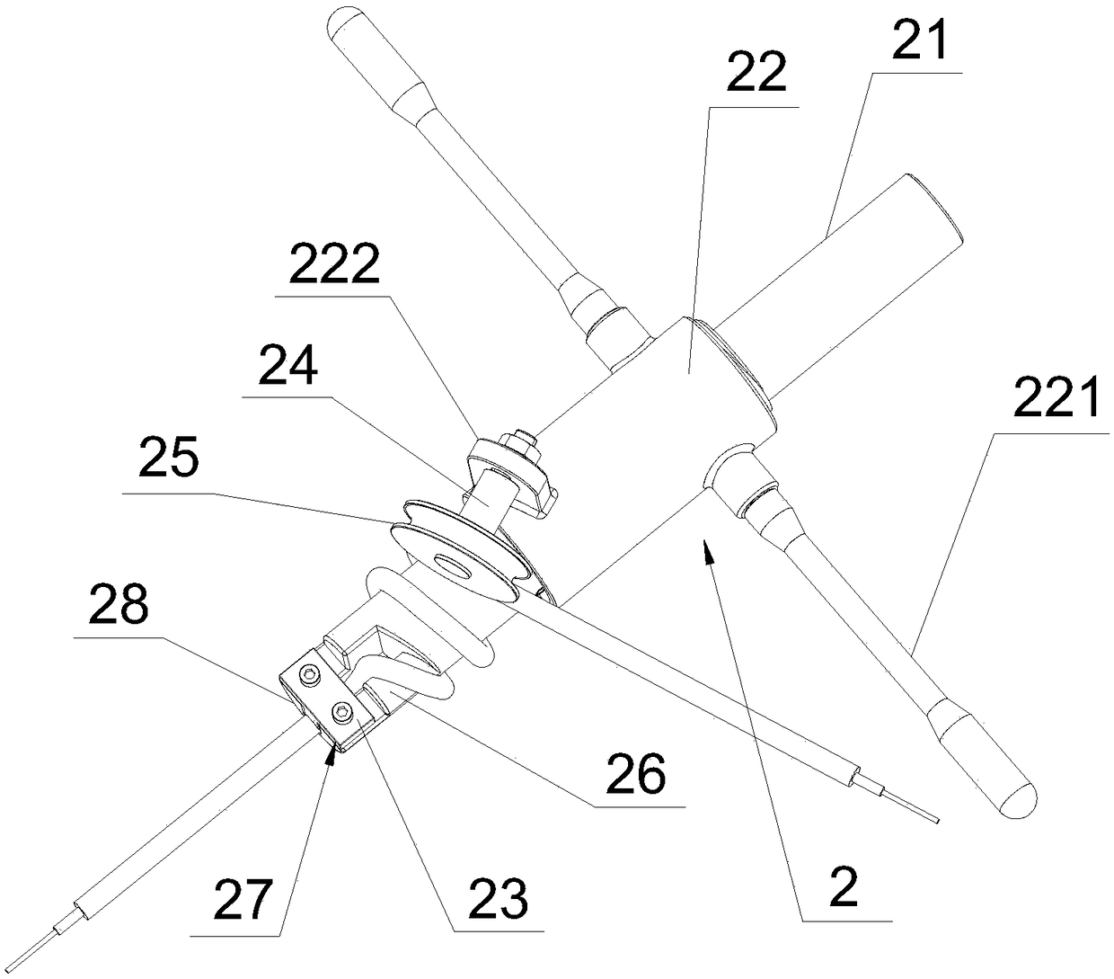
[0038] see figure 2As shown, the embodiment of the present invention provides a molding device for eccentric spiral optical cable pigtails, including a second mold 2 for bending the middle part of the helical section of optical cable pigtails. The second mold 2 includes a rotating core 21 and a sleeve The rotary nut 22 arranged on the rotary mold core 21, the rotary mold core 21 is cylindrical, and one end of the rotary mold core 21 is provided with a first semicircle arc section 26, and the first semicircle arc section 26 The side away from the rotating mold core 21 is provided with a first fixing structure 27 for fixing the optical cable pigtail, the first fixing structure includes a first base and a detachable first pressing block 23, the first The base 28 is provided with a first groove along the axial direction of the rotating mold core 21, the first groove and the first pressing block 23 cooperate to fix the optical cable pigtail, and the middle part of the rotating mol...
Embodiment 2
[0040] The embodiment of the present invention provides a forming device for eccentric spiral optical cable pigtails. The difference from Embodiment 1 is that the rotating nut 22 is provided with a second fixing seat 222 at the end close to the first fixing structure 27, The rotating nut 22 is fixed to the rotating shaft 24 through the second fixing seat 222, and the rotating shaft 24 can move relative to the rotating mold core 21 on the second fixing seat 222, and the set The second fixing seat 222 can make the rotating shaft 24 arranged on it move relative to the rotating core 21, and can facilitate placing the optical cable pigtails in the second section, while avoiding the rotation caused by the rotating core. 21 and the second pressure wheel 25 is so small that the surface of the pigtail of the optical cable is damaged.
Embodiment 3
[0042] The embodiment of the present invention also provides a method for forming a spiral optical cable pigtail using the forming device described in Embodiment 1, comprising the following steps:
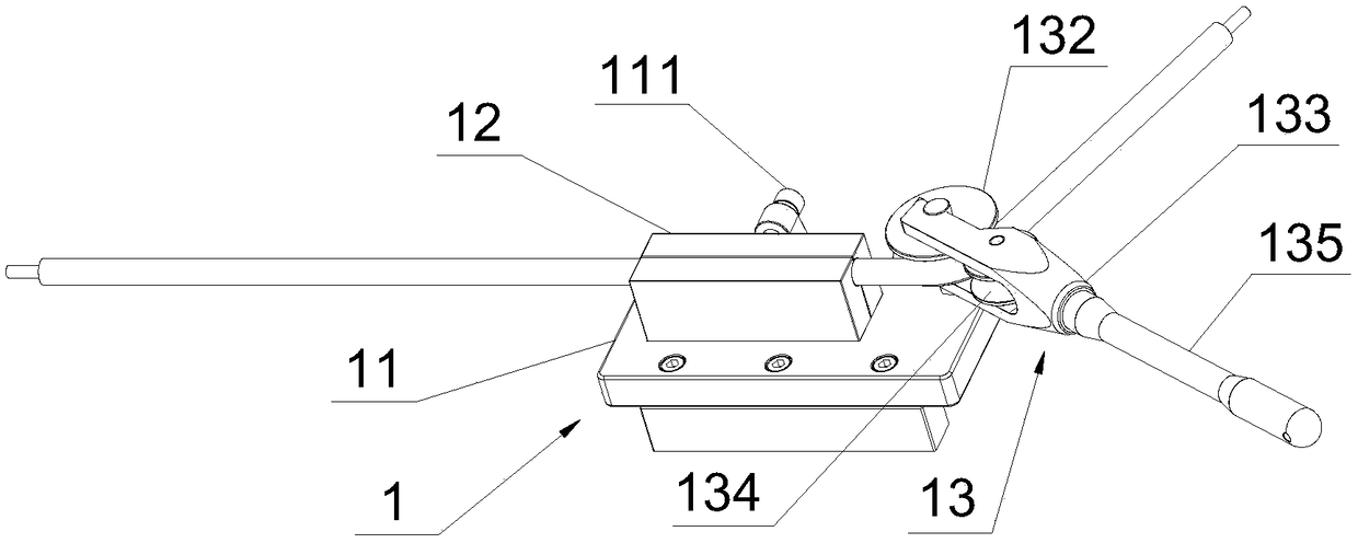
[0043] S1: see figure 1 As shown, a first mold 1 for bending the front end of the helical section of the optical cable pigtail is provided, and the first mold 1 includes a fixing plate 11, a clamp 12 and a first bending assembly 13 arranged on the fixing plate 11, and the The clamp 12 is provided with a straight channel that matches the shape of the optical cable pigtail, and the first bending assembly 13 includes a wheel 132 assembled on the fixed plate 11 and is detachably connected with the wheel 132 and can be wound around. The rotating member 133 that the rotating wheel 132 rotates on its axis, and a first pressing wheel 134 is rotated on the rotating member 133, and the first pressing wheel 134 and the rotating wheel 132 are formed to match the shape of the optical cable pigt...
PUM
 Abstract
Description
Claims
Application Information