Supercharge Your Innovation With Domain-Expert AI Agents!

Vehicle anti-glare rear view mirror manufacturing method and vehicle anti-glare rear view mirror

A manufacturing method and rearview mirror technology, which is applied in the field of vehicle rearview mirrors, can solve the problems of colloid thickness rebound, box thickness unevenness, etc., and achieve the effects of preventing rebound, convenient curing, and good thickness uniformity

Inactive Publication Date: 2018-12-21
TRULY OPTO ELECTRONICS
View PDF6 Cites 0 Cited by
  • Summary
  • Abstract
  • Description
  • Claims
  • Application Information

AI Technical Summary

Problems solved by technology

After dispensing and bonding, the product is removed from the bonding equipment, and the thickness of the colloid will rebound during the period before curing (the rebound deviation ranges from 20 μm to 40 μm), which eventually leads to uneven thickness of the box

Method used


Image

  • Vehicle anti-glare rear view mirror manufacturing method and vehicle anti-glare rear view mirror
  • Vehicle anti-glare rear view mirror manufacturing method and vehicle anti-glare rear view mirror

Examples


Embodiment 1

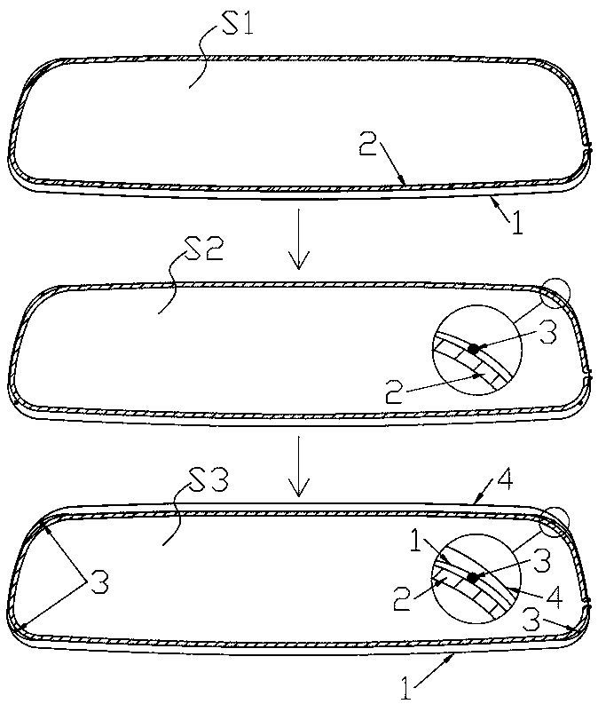
[0029] Such as figure 1 As shown, the embodiment of the present invention provides a method for manufacturing a vehicle-mounted anti-glare rearview mirror, comprising the following steps:

[0030] S1: Provide the lower functional substrate 1 and clamp it with the first bonding fixture, and apply heat-curable sealant 2 around the side of the lower functional substrate 1 with the conductive layer;

[0031] S2: Spot UV glue 3 on the four corners of the side of the lower functional substrate 1 with the conductive layer 5;

[0032] S3: Provide an upper functional substrate 4 and clamp it with the second bonding fixture, and attach the side of the upper functional substrate 4 with the conductive layer 5 to the side of the lower functional substrate 1 with the conductive layer 5 The position of the bonding equipment corresponding to the UV glue 3 is transparent or avoids the air;

[0033] S4: Use UV light to cure UV glue 3 immediately after bonding;

[0034] S5: The first and seco...

Embodiment 2

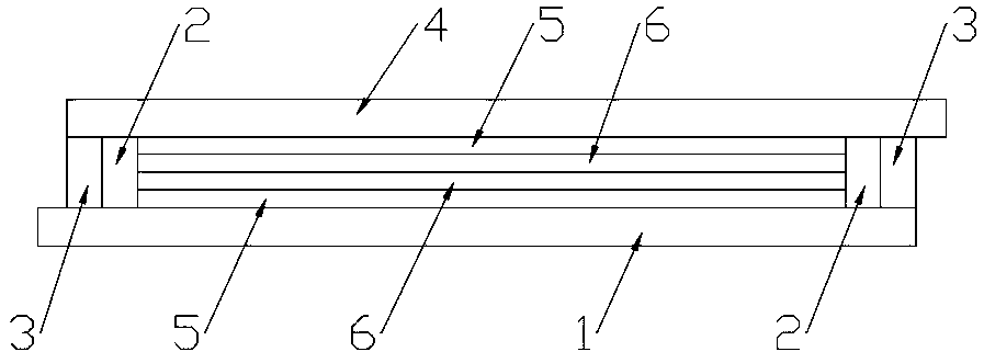
[0041] Such as figure 2As shown, the embodiment of the present invention provides a vehicle-mounted anti-glare rearview mirror, including a lower functional substrate 1 and an upper functional substrate 4 oppositely arranged, and the lower functional substrate 1 faces the upper functional substrate One side of 4 is surrounded by heat-curable frame glue 2, and UV glue 3 is provided at the four corners of the side of the lower functional substrate 1 facing the upper functional substrate 4, and the lower functional substrate 1 and the upper functional substrate 4 are bonded and fixed by UV glue 3 and thermosetting frame glue 2.

[0042] In the embodiment of the present invention, by setting a thermosetting frame glue 2 and a UV glue 3 on the lower functional substrate 1 at the same time, the rebound of the thermosetting glue 2 is effectively prevented, so that the lower functional substrate 1 and the upper functional substrate 4 are bonded together. The thickness uniformity aft...


PUM

PropertyMeasurementUnit
diameteraaaaaaaaaa
heightaaaaaaaaaa

Abstract

The present invention discloses a vehicle anti-glare rear view mirror manufacturing method and structure, wherein the method comprises following steps: providing a lower functional substrate, clampingthe lower functional substrate with a first bonding fixture, and dispensing thermosetting frame glue on the periphery of one side, having a conductive layer, of the lower functional substrate; dispensing UV glue on four corners of the side, having a conductive layer, of the lower functional substrate, wherein the UV glue is formed on the periphery of the thermosetting frame glue; providing an upper functional substrate, clamping the upper functional substrate with a second bonding fixture, and aligning and bonding one side, having a conductive layer, of the upper functional substrate with theside, having the conductive layer, of the lower functional substrate, wherein positions, corresponding to the UV glue, of a bonding device are transparent or in clearance; after bonding, immediatelycuring the UV glue with ultraviolet light; and taking off the first bonding fixture and the second bonding fixture, and then curing the thermosetting frame glue of the lower functional substrate and the upper functional substrate after the bonding. The method effectively prevents the thermosetting frame glue from rebounding, so that thickness uniformity is good after bonding of the lower functional substrate and the upper functional substrate.

Description

technical field [0001] The invention relates to the technical field of vehicle-mounted rearview mirrors, and in particular to a method for manufacturing a vehicle-mounted anti-glare rearview mirror and the vehicle-mounted anti-glare rearview mirror. Background technique [0002] When the driver is driving at night, if there is a car running behind, the light of the headlight shines on the rearview mirror, and the strong light of the light will cause glare to the driver's eyes, and the eyes will be dark in an instant. At this time, if there are vehicles or pedestrians in front, traffic accidents will easily occur; the anti-glare principle of the rearview mirror is that when the strong light shines on the rearview mirror, the sensor on the mirror sends the light signal to the microcomputer, and after signal processing, The control circuit will change the color of the mirror to absorb strong light and reduce the reflection of strong light. The thickness uniformity of the EC ma...

Claims


Application Information

Patent Timeline
Patent Type & Authority Applications(China)
IPC IPC(8): G02F1/15G02F1/153B60R1/08
CPCB60R1/088G02F1/15G02F1/153
Inventor 冯毅周伟杰
Owner TRULY OPTO ELECTRONICS
Features
  • R&D
  • Intellectual Property
  • Life Sciences
  • Materials
  • Tech Scout
  • Unparalleled Data Quality
  • Higher Quality Content
  • 60% Fewer Hallucinations
Learn More