

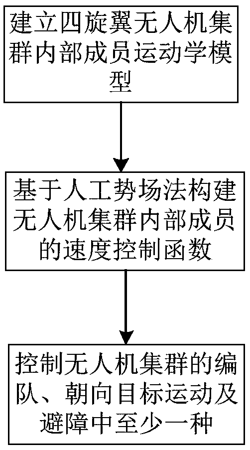
Artificial potential field method-based quad-rotor unmanned aerial vehicle cluster control method and device therefor
A technology of quadrotor UAV and artificial potential field method, which is applied in the direction of non-electric variable control, control/regulation system, three-dimensional position/channel control, etc. low level problem
- Summary
- Abstract
- Description
- Claims
- Application Information
AI Technical Summary
Problems solved by technology
Method used
Image

Examples
Embodiment 1
[0196] Embodiment 1 controls the simulation test of unmanned aerial vehicle swarm formation
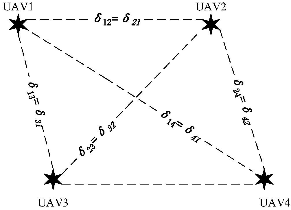
[0197] The number of UAVs is taken as 4, and the parameters of the formula (6) are: a=5, b=0.5, c=0.1, and the preset formation structure is as follows Figure 4 shown.
[0198] The position of the target point is taken as: a(30,50,10), b(30,50,40), c(30,10,40), d(30,10,10), the unit is m, and no one is known The preset formation of UAVs is a rectangle, and the speed of each UAV satisfies the speed constraint of formula (2). Assume the maximum velocity V of the drone max =30m / s, the simulation results of UAV swarm formation control are as follows Figure 5 shown.
[0199] The formation used in this embodiment 1 includes 4 quadrotor UAVs, and the initial positions of the 4 quadrotor UAVs are randomly distributed, by Figure 5 It can be seen that after moving to the final position, a preset rectangular formation is formed (the speed of each UAV is 0 at this time), and the relative ...
Embodiment 2
[0200] Embodiment 2 Controlling the UAV swarm towards the target motion simulation experiment
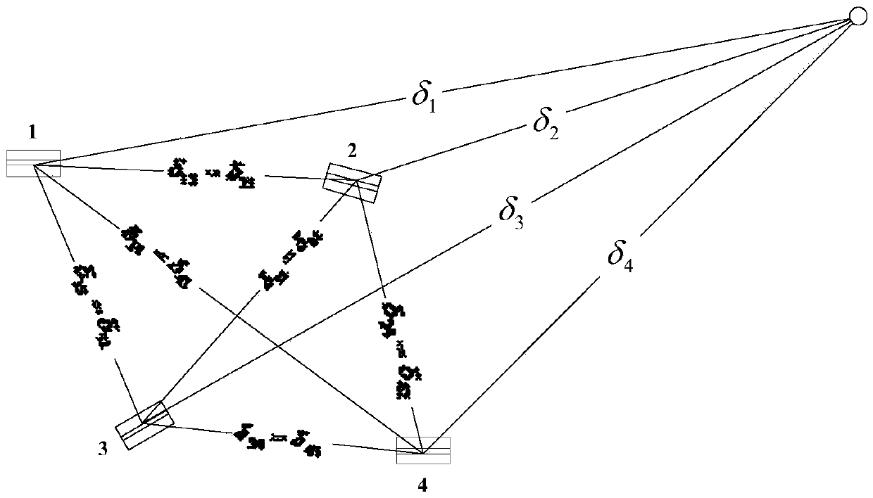
[0201] In the simulation experiment, in this embodiment 2, 6 quadrotor UAVs and 1 virtual leader are used to form a cluster formation. The preset formation of the UAV cluster is as follows: Image 6 As shown, the 6 light-colored squares represent the UAV nodes, and the dark-colored squares represent the virtual leader. The 6 quadrotor UAVs take the virtual leader as the top angle and form an equilateral triangle formation configuration on one side of the virtual leader. .
[0202] In the simulation test of Example 2, first, set the speed parameter a to 5, and the virtual point position to (35,35,30), unit: m, which is also the target point position. In the drone cluster configuration, 6 drones are in the same plane, and the plane normal vector of the final position of the drone is taken as
[0203] The motion track diagram of UAV cluster in three-dimensional space is as follows:...
Embodiment 3
[0204] Embodiment 3 Control UAV cluster obstacle avoidance simulation experiment
[0205] In this embodiment, the aforementioned obstacle avoidance algorithm is used to carry out the UAV cluster obstacle avoidance simulation. In the simulation experiment, the number of UAV members is 8, and the formation configuration is as follows: Figure 8 As shown, the square represents the UAV, and the circle represents the center position of the UAV cluster.
[0206] For the convenience of observation, the position of the UAV cluster is projected onto the x-y plane for analysis. The position of the cluster target is as follows: Figure 9 As shown, when the UAV swarm moves to the target position, it will form a square configuration, and the target position of its center point is taken as (60, 60, 60) (unit: m).
[0207] Then set up the obstacle position. In this paper, two spherical obstacles are placed with radii of 3 and 4 respectively, and their projections on the x-y plane are as fo...
PUM
 Abstract
Description
Claims
Application Information