
Precise modeling method of gear considering microcosmic modification and actual machining error

A machining error, practical technology, applied in the field of gear modeling and machining, can solve the problem of not comprehensively considering the micro modification machining error and so on

Active Publication Date: 2018-12-21
CHINA FIRST AUTOMOBILE
View PDF6 Cites 11 Cited by
  • Summary
  • Abstract
  • Description
  • Claims
  • Application Information

AI Technical Summary

Problems solved by technology

[0004]However, in the existing gear modeling methods, only one aspect of microscopic modification or machining error is considered, and microscopic modification and actual machining are not considered comprehensively. error

Method used


Image

  • Precise modeling method of gear considering microcosmic modification and actual machining error
  • Precise modeling method of gear considering microcosmic modification and actual machining error
  • Precise modeling method of gear considering microcosmic modification and actual machining error

Examples


Embodiment Construction

[0062] In order to make the technical problems, technical solutions and advantages to be solved by the present invention clearer, a detailed description will be given below in conjunction with the accompanying drawings and specific embodiments.

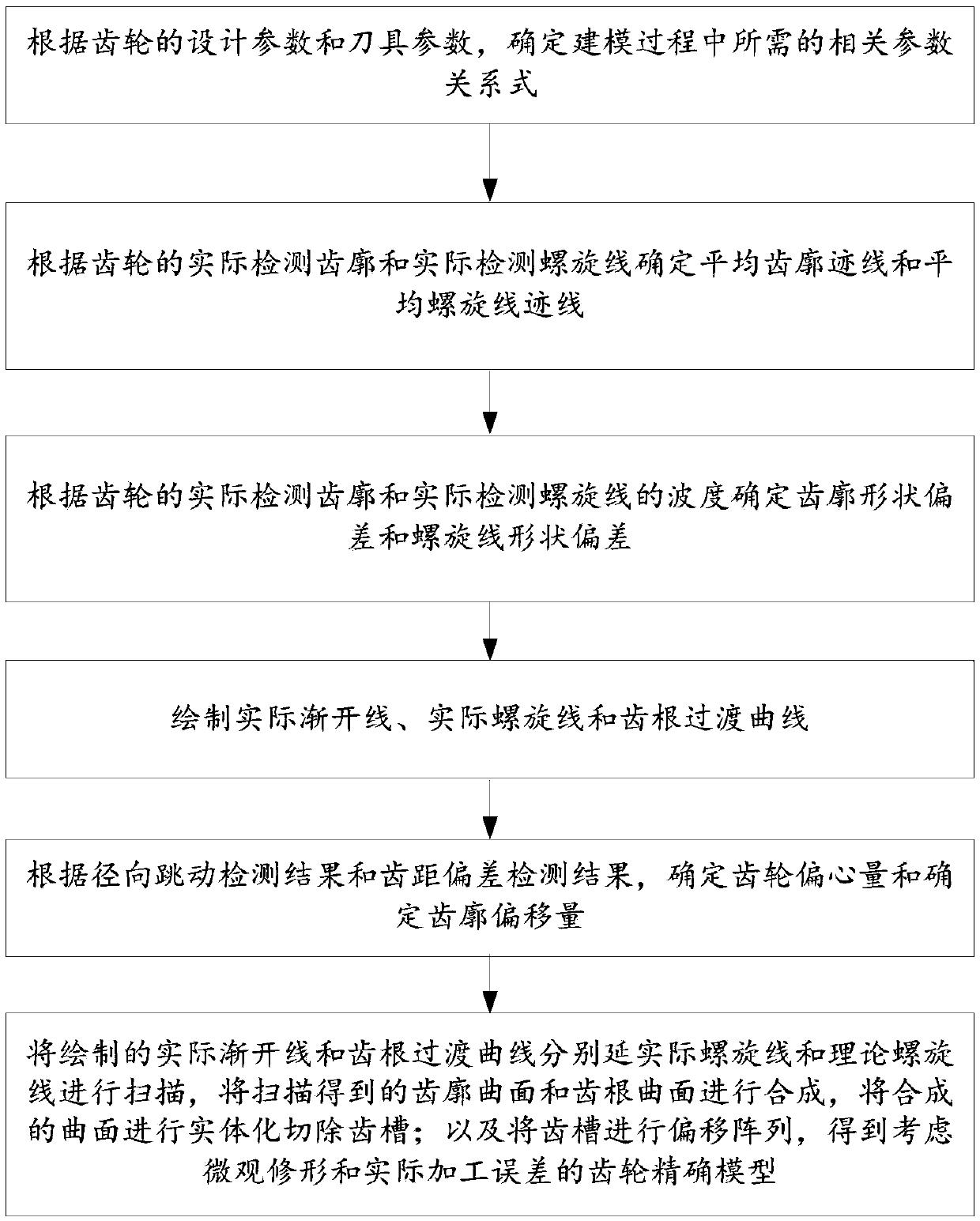
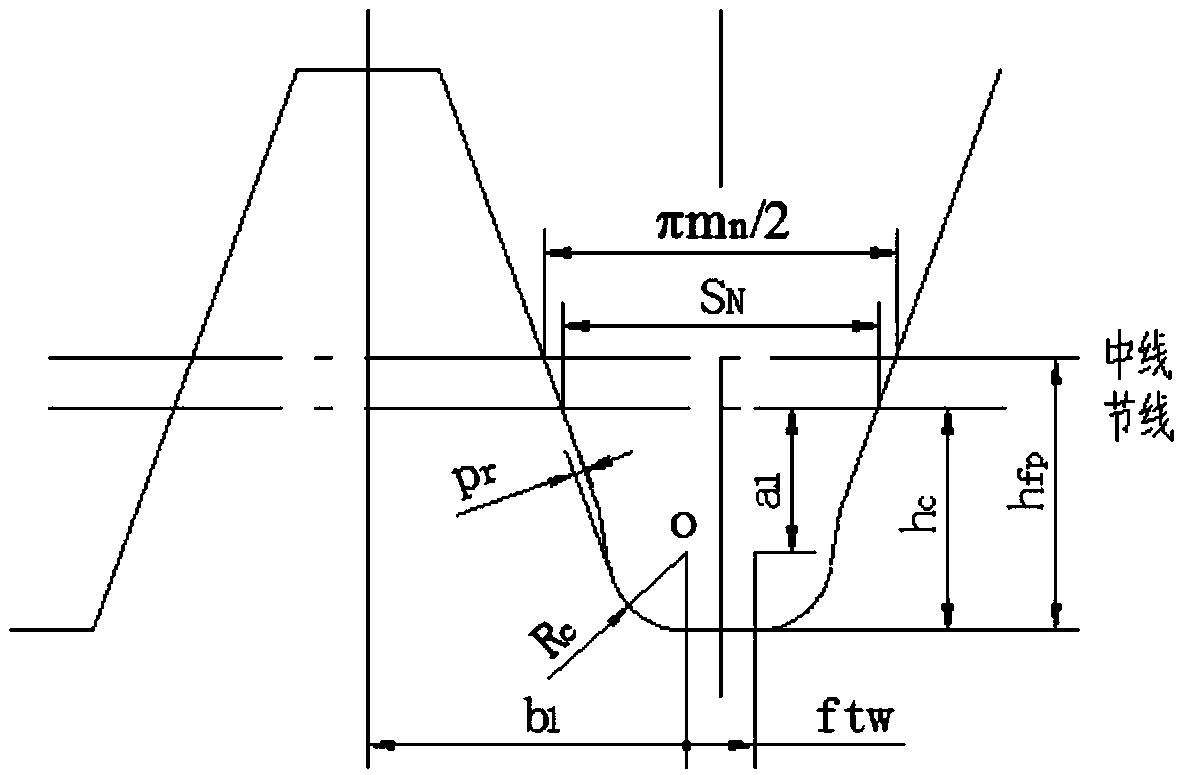
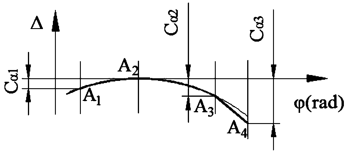
[0063] figure 1 Is a schematic flow diagram of a gear modeling method provided by an embodiment of the present invention; figure 2 It is a schematic diagram of tool structure parameters; image 3 It is a schematic diagram of the average tooth profile trace of the detection gear; Figure 4 It is a schematic diagram of the average spiral trace of the detection gear; Figure 5 It is a schematic diagram of the actual tooth profile trace of the detection gear; Image 6 It is a schematic diagram of the actual spiral trace of the detection gear; Figure 7 Is the actual involute diagram; Figure 8 It is a schematic diagram of the actual base circle helix of the right-handed gear; Picture 9 It is a schematic diagram of the actual base circle helix...


PUM


Abstract

The invention provides an accurate modeling method of a gear considering microcosmic modification and actual machining error. The method firstly derives the necessary parameters of the gear and the cutter required in the modeling process. According to the actual detection of gear tooth profile and actual detection of helix, the average tooth profile trace and the average helix trace of gear are obtained. According to the actual detection of tooth profile and the actual detection of helix waviness, tooth profile shape deviation and helix shape deviation are obtained. According to the results ofradial runout and tooth pitch deviation detection, the eccentricity of the gear and the offset of the actual tooth profile are obtained. In three-dimensional software, the actual involute, the actualbase circle helix and the tooth root transition curve are plotted, and the tooth profile offset array is carried out. Finally, in the software, the surface is scanned, trimmed and merged, the tooth alveoli are removed, and the precise three-dimensional model is obtained after shifting the array. The gear model established by this method can simulate the meshing state of the actual machined gearsand predict the failure form and service life of the gears.

Description

Technical field [0001] The invention relates to a gear accurate modeling method, in particular to a gear accurate modeling method considering microscopic modification and actual machining errors, and belongs to the field of gear modeling and processing. Background technique [0002] At present, the calculation method of gear strength check is generally carried out in accordance with the ISO6336 standard. When considering the influence of gear micro-modification and machining error on the gear strength, the calculation results are corrected by various coefficients. The purpose of gear micro-modification is to effectively improve the meshing state of the gear. Gear machining errors will cause problems such as gear tooth orientation, uneven load distribution between teeth, tooth root and tooth tip interference, and increased gear transmission errors. The selection of various coefficients in the standard is generally carried out according to empirical charts or empirical formulas. [...

Claims


Application Information

Patent Timeline
IPC IPC(8): G06F17/50
CPCG06F30/17G06F30/23
Inventor 孙友情李松松陈德鑫魏寒张嘉策
Owner CHINA FIRST AUTOMOBILE
Learn More