A switch converter

A switching converter, step-down circuit technology, applied in instruments, converting DC power input to DC power output, adjusting electrical variables, etc. No-load power consumption, improve circuit stability, and save costs

Inactive Publication Date: 2018-12-21
MORNSUN GUANGZHOU SCI & TECH
View PDF4 Cites 5 Cited by
  • Summary
  • Abstract
  • Description
  • Claims
  • Application Information

AI Technical Summary

Problems solved by technology

However, if the duty cycle is too small or too narrow, it will easily lead to problems such as unstable control and unreliable turn-on of the power tube, which will greatly reduce the performance of the circuit.
Another problem is: the control and drive generally use a voltage of about 12V for power supply. If only one-stage step-down converter is used, the voltage can only be stepped down from the rectified and filtered high-voltage side, or boosted from the output low-voltage side. Electricity, to provide voltage for control and drive, which will increase the cost and reduce the efficiency of the circuit
From the above two problems, it is difficult to meet the requirements of performance and no-load power consumption by using only one-stage buck converter topology, which limits its application range

Method used


Image

  • A switch converter
  • A switch converter
  • A switch converter

Examples


no. 1 example

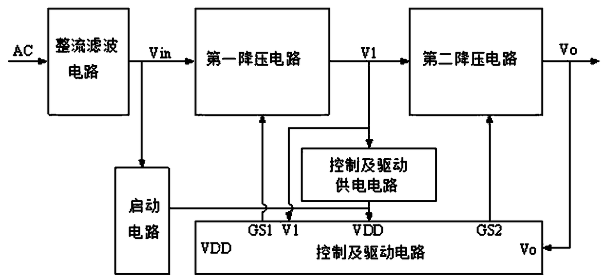
[0033] figure 2 It is the circuit schematic diagram of the first embodiment of the switching converter of the present invention, and the composition and connection relationship of each module are as follows:

[0034] Rectification and filtering circuit: including rectification bridge DB1 and capacitor C1, the input of rectification bridge DB1 is the input terminal of rectification and filtering circuit, the input negative of rectification bridge DB1 is the input ground of rectification and filtering circuit, the output of rectification bridge DB1 is serving as rectification and filtering circuit The output terminal of the rectifier bridge DB1, the output negative of the rectifier bridge DB1 is used as the output ground of the rectifier filter circuit, and as the common ground Vin- of the switching converter, and the capacitor C1 is connected between the output positive and output negative of the rectifier bridge DB1; the rectifier filter circuit receives the input The AC volt...

no. 2 example

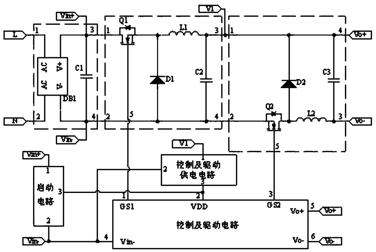
[0046] Figure 5 It is the circuit schematic diagram of the switching converter of this embodiment. The difference from the first embodiment is that the second step-down circuit adopts a synchronous rectification method to realize the same reference ground of the first step-down circuit and the second step-down circuit. It is beneficial for the control and driving circuit to sample and control the first and second step-down circuits. The second step-down circuit includes a MOS transistor Q2, a MOS transistor Q3, a capacitor C3, and an inductor L2. The connection relationship is: the drain of the MOS transistor Q2 is the input terminal of the second step-down circuit, and the source of the MOS transistor Q2 is connected to the MOS transistor The drain of Q3 and one end of the inductor L2; the gate of the MOS transistor Q2 is used as the first control terminal of the second step-down circuit; the other end of the inductor L2 is connected to one end of the capacitor C3, and is us...


PUM


Abstract

The invention discloses a switching converter, which comprises a rectifying filter circuit, a first step-down circuit, a second step-down circuit, a starting circuit, a control and driving circuit anda control and driving power supply circuit. A two-stage cascade step-down circuit is adopted in the invention, the output of the first step-down circuit serves as inputs to the second step-down circuit and the control and driving power supply circuit, At the same time, the output of the first step-down circuit is control and processed by the control and drive power supply circuit to supply the working voltage as the output of the control and driving circuit, the control and driving circuit collects the output voltages of the first buck circuit and the second buck circuit in real time to driveand control the on and off of the power transistor in the two-stage cascaded buck circuit, By adjusting the duty cycle of the two-stage buck circuit, the output voltage can be adjusted, which can notonly meet the requirements of high buck ratio, but also avoid the small and narrow duty cycle, and greatly reduce the no-load power consumption and improve the performance of the circuit.

Description

technical field [0001] The invention relates to a switching converter, in particular to a non-isolated step-down switching converter with a high step-down ratio. Background technique [0002] In the actual application of the power converter, there is no requirement for electrical isolation between the input and output in some occasions, but there are higher requirements for the performance of the circuit and no-load power consumption. It is necessary to directly convert the rectified mains power into low-voltage power to supply power to the load, such as an output voltage of 5V. At the same time, the no-load power consumption of the circuit is required to meet the six-level energy efficiency standard of switching power supply. [0003] Generally, the input AC voltage of the power converter ranges from 85V to 265V, and the rectified and filtered DC voltage is about 100V to 375V. If only a single-stage step-down converter is used, when the circuit works in a steady state, the...

Claims


Application Information

Patent Timeline
Patent Type & Authority Applications(China)
IPC IPC(8): H02M3/156H02M1/08
CPCH02M1/08H02M3/156H02M1/007
Inventor 吴辉郭启利王志燊李永昌
Owner MORNSUN GUANGZHOU SCI & TECH
Why Eureka
Try Eureka