
Rigid-flexible bonding panel solar array

A technology of solar cell array and rigid-flex panel, applied in the field of rigid-flex panel solar cell array, can solve problems such as failure to achieve electrical connection, solar wings cannot maximize the area of ​​the solar array, etc., and achieves low cost, low development cycle short effect

Inactive Publication Date: 2018-12-21
SHANGHAI INST OF SPACE POWER SOURCES
View PDF8 Cites 4 Cited by
  • Summary
  • Abstract
  • Description
  • Claims
  • Application Information

AI Technical Summary

Problems solved by technology

However, this type of solar wing does not realize the electrical connection between different PCB boards, forming a foldable and retractable solar cell array, and the solar wing cannot maximize the area of ​​the solar array within the limited envelope size.

Method used


Image

  • Rigid-flexible bonding panel solar array

Examples


Embodiment Construction

[0017] In order to make the above objectives, features and advantages of the present invention more obvious and understandable, the present invention will be further described in detail below with reference to the accompanying drawings and specific embodiments.

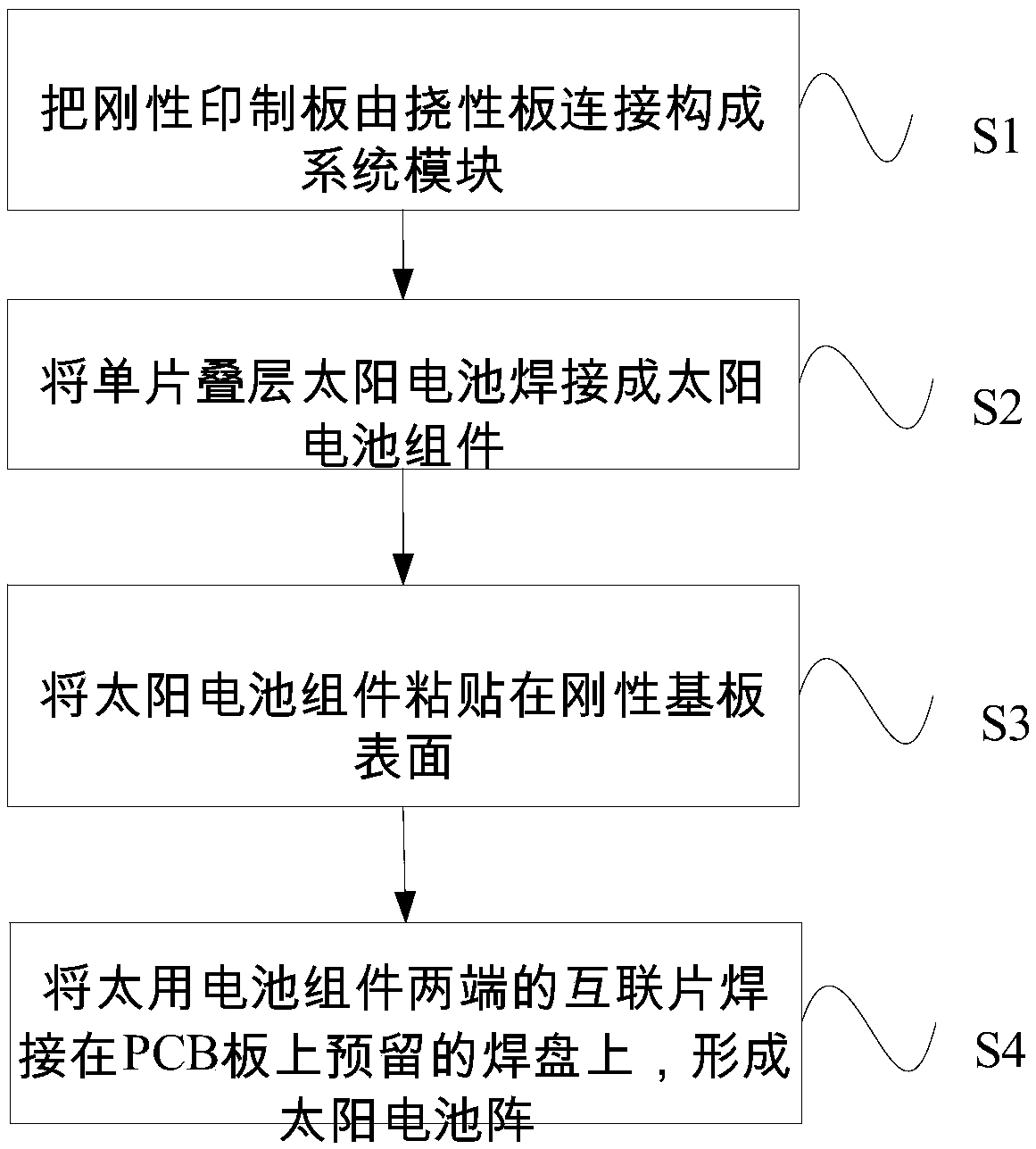
[0018] Such as figure 1 As shown, the present invention provides a rigid-flex panel solar cell array, including:

[0019] A plurality of rigid substrates, each of which is integrated with a solar cell module, wherein each rigid substrate is connected by a flexible board, and the flexible board realizes the electrical transmission between the rigid substrates, thereby forming the electrical power of the solar cell array. connection.

[0020] Here, the present invention integrates the solar cell module and the substrate, the substrate and the substrate are integrated through the flexible board, and the solar cell array is formed through the integration of the solar cell module and the substrate. This type of solar array is a ...


PUM

PropertyMeasurementUnit
Plate thicknessaaaaaaaaaa

Abstract

A rigid-flexible bonding plate solar cell array the invention is integrated with a substrate through a solar cell module, A substrate and a substrate are connected with each other through a flexible board to realize circuit connection, so as to form a solar cell array in which the solar cell circuit and the substrate are completely integrated, This kind of solar array is a folding type, which saves wires and cables, makes full use of the limited envelope space of micro-satellites, maximizes the area of solar array, realizes the maximum output of solar array electric power in the limited envelope range, meets the satellite power supply demand, and solves the problem that the solar wing of micro-satellites is limited by the envelope size of stars.

Description

Technical field [0001] The invention relates to a rigid-flex panel solar cell array. Background technique [0002] Micro-satellites are one of the hot spots in the aerospace field and an inevitable product of the development of aerospace technology. Its outstanding advantages are small size, light weight, low cost, short cycle, and wide application fields. It has been an important supplement to large satellites. Many fields, such as remote sensing, remote sensing, scientific research, and technology demonstration, are increasingly showing their unique advantages. Microsatellites have adopted new design technologies such as integration and modularization. With the increase of the effective load, its power demand is also increasing. It is necessary to achieve a larger deployment area within a limited envelope volume. Therefore, similar solar wings on large satellites have appeared. Due to size limitations, their solar panels generally adopt thickness Thinner PCB or carbon fiber co...

Claims


Application Information

Patent Timeline
IPC IPC(8): H02S30/20H02S40/36
CPCH02S30/20H02S40/36Y02E10/50
Inventor 仇恒抗杨广刘咏晖黄三玻苏宝法王文强
Owner SHANGHAI INST OF SPACE POWER SOURCES
Learn More