Pulse wave detection device and biological information measurement device

A detection device and pulse wave technology, which is applied in diagnostic recording/measurement, medical science, diagnosis, etc., can solve the problems of setting multiple element rows and not having specific records, and achieve the effect of improving detection accuracy

A detection device and pulse wave technology, which is applied in diagnostic recording/measurement, medical science, diagnosis, etc., can solve the problems of setting multiple element rows and not having specific records, and achieve the effect of improving detection accuracy

CN109069020BActive Publication Date: 2021-09-03OMRON HEALTHCARE CO LTD

Image

  • Pulse wave detection device and biological information measurement device
  • Pulse wave detection device and biological information measurement device
  • Pulse wave detection device and biological information measurement device

Examples


Embodiment Construction

[0052] Embodiments of the present invention will be described below with reference to the drawings.

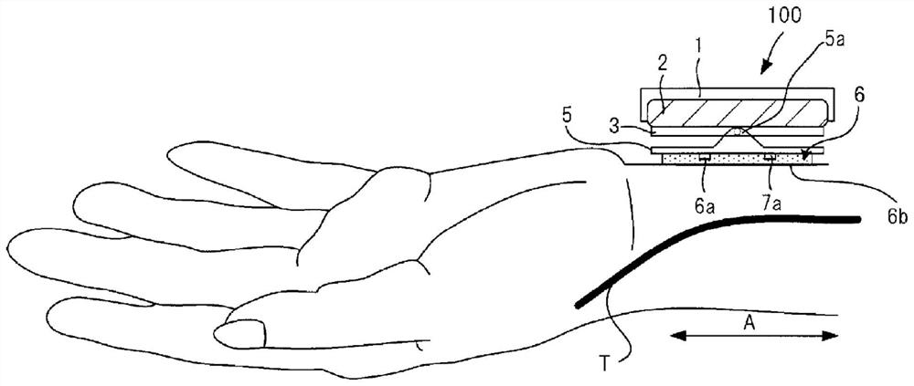
[0053] figure 1 It is a schematic diagram showing the external configuration of the pulse wave detection unit 100 of the biological information measurement device according to one embodiment of the present invention. The biological information measuring device of this embodiment is worn on the body part ( figure 1 For example, the wrist of the user's left hand) in which there is an artery ( figure 1 In our example, the radial artery T).

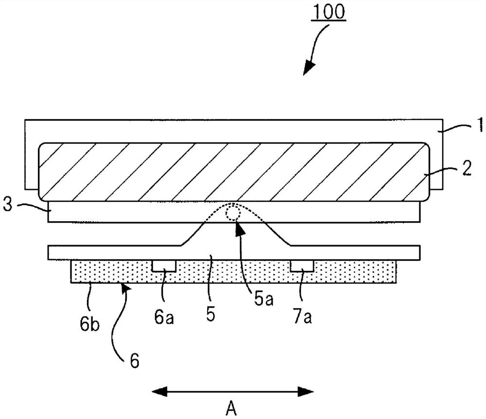
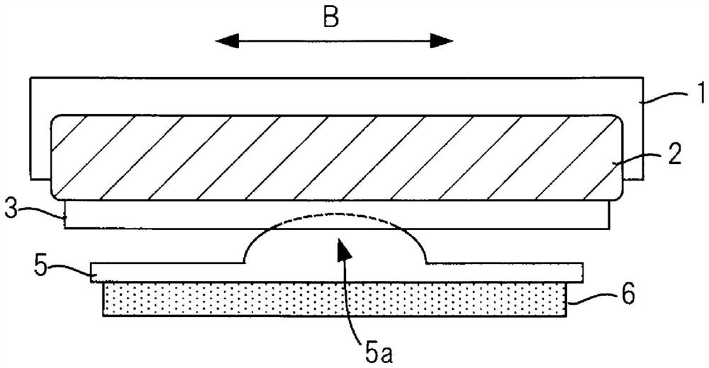
[0054] figure 2 yes figure 1 An enlarged view of the pulse wave detection unit 100 shown. image 3 is viewed from the user's elbow figure 1 A diagram of the pulse wave detection unit 100 in the wearing state shown. Figure 4 It is viewed from the side of the contact part in contact with the wrist figure 1 A diagram of the pulse wave detection unit 100 in the wearing state shown. Figure 1 ~ Figure 4 It is used to schematically repre...


PUM


Abstract

The present invention provides a pulse wave detection device capable of improving the detection accuracy of a pulse wave, and a biological information measuring device including the pulse wave detection device. The pulse wave detection unit (100) includes: a sensor unit (6), an element row (60, 70) is formed by a plurality of pressure detection elements arranged along the direction (B), and the two element rows (60, 70) are along The direction (A) perpendicular to the direction (B) is arranged; and the air bag (2) presses the sensor part ( 6). The arrangement interval (distance L1) of the two element rows (60, 70) in the direction (A) is not less than 5 mm and not more than 15 mm.

Description

technical field [0001] The present invention relates to a pulse wave detection device and a biological information measurement device. Background technique [0002] There is known a biological information measuring device capable of measuring pulse, heart rate, or blood pressure using information detected by the pressure sensor in a state where the pressure sensor is brought into contact with the body surface of a living body part through which arteries such as the radial artery of the wrist pass. and other biological information (see Patent Document 1). [0003] Patent Document 1 discloses a biological information measurement device having a driving unit that surrounds a pressure sensor having a plurality of element rows composed of a plurality of pressure detection elements in a direction that is in the same direction as the arrangement direction of the plurality of element rows. The axis extending in the orthogonal direction (orthogonal to the artery) is rotated. This b...

Claims


Application Information

Patent Timeline
03 Sep 2021
Publication
CN109069020B
IPC
A61B5/02
CPC
A61B5/6843; A61B5/02438; A61B5/02444; A61B2562/046; A61B5/6824; A61B5/02108; A61B5/02141; A61B5/022
Inventors
北川毅; 山下新吾