Coupling configuration and catheter having the same
A technology for structuring and tubular parts, applied in the direction of conduits, connecting pipes, pipes/pipe joints/fittings, etc., can solve the problems of weak joint strength, cracks in the stepped part, and cracks in the tapered part, etc., to achieve increased joint strength and joint The effect of increasing the area and increasing the joint strength
- Summary
- Abstract
- Description
- Claims
- Application Information
AI Technical Summary
Problems solved by technology
Method used
Image


Examples
no. 1 approach
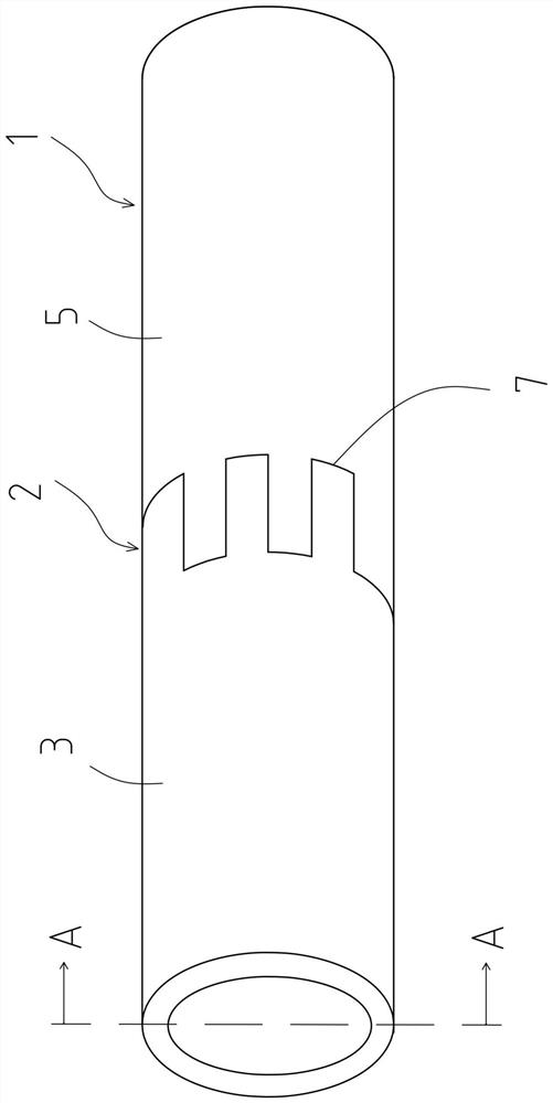
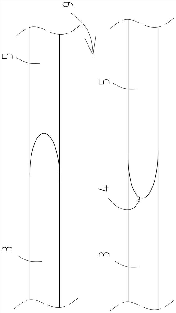
[0036] figure 1 It is a perspective view of the joint structure of the first embodiment of the present invention, figure 2 It is cut in the A-A direction figure 1 A cross-sectional view of the vicinity of the joint during the joint structure, image 3 It is a front view near the junction part of the junction structure of 1st Embodiment, Figure 4 is recorded image 3 Front view near junction of entry vertices in .
[0037] exist figure 1 In the joint structure 1, a tubular member 3 made of resin and a tubular member 5 made of resin are joined, and the joint surface 7 in the joint portion 2 of the tubular member 3 and the tubular member 5 is aligned in the longitudinal direction along the circumferential direction of the tubular member. Convex shape.
[0038] In addition, if figure 1 As shown, the concave-convex shape in this embodiment is a substantially rectangular shape along the circumferential direction of the tubular member.
[0039] Here, the joint surface 7 of ...
no. 2 approach
[0049] Hereinafter, a second embodiment of the present invention will be described.
[0050] Figure 5 It is a front view showing the vicinity of the junction of the entry apex 14 in the junction structure 11 according to the second embodiment.
[0051] exist Figure 5 In the joint structure 11, the tubular member 13 made of resin and the tubular member 15 made of resin are joined, and the joint surface 17 in the joint portion 12 of the tubular member 13 and the tubular member 15 is in the long axis direction along the circumferential direction of the tubular member. Convex shape.
[0052] In addition, the concave-convex shape in this embodiment is also the same as the joining structure 1 of the first embodiment, and is substantially rectangular in the circumferential direction of the tubular member.
[0053] Therefore, in the joint structure 11 of the present embodiment, the joint surface 17 in the joint portion 12 of the tubular member 13 and the tubular member 15 also ha...
no. 3 approach
[0058] Hereinafter, a third embodiment of the present invention will be described.
[0059] Image 6 It is a front view of the vicinity of the joint part of the joint structure 21 of the third embodiment, Figure 7 is in Image 6 A front view of the vicinity of the joint that enters the apex 24 is added with a dotted line.
[0060] exist Image 6 In the joint structure 21, the tubular member 23 made of resin and the tubular member 25 made of resin are joined, and the joint surface 27 in the joint portion 22 of the tubular member 23 and the tubular member 25 is in the longitudinal direction along the circumferential direction of the tubular member. Convex shape.
[0061] In addition, if Image 6 As shown, the concave-convex shape of this embodiment is a wave shape along the circumferential direction of the tubular member.
[0062] Here, as in the first and second embodiments, the joining surface 27 of the tubular member 23 and the tubular member 25 is made to have a conve...
PUM
 Abstract
Description
Claims
Application Information
 - Generate Ideas
- Intellectual Property
- Life Sciences
- Materials
- Tech Scout
- Unparalleled Data Quality
- Higher Quality Content
- 60% Fewer Hallucinations
Browse by: Latest US Patents, China's latest patents, Technical Efficacy Thesaurus, Application Domain, Technology Topic, Popular Technical Reports.
© 2025 PatSnap. All rights reserved.Legal|Privacy policy|Modern Slavery Act Transparency Statement|Sitemap|About US| Contact US: help@patsnap.com