
Transport method for transferring workpieces

A workpiece and transportation device technology, which is applied in the field of transportation for conveying workpieces, can solve problems such as damage to transportation devices or processing equipment, failure to shape workpieces as expected, and achieve the effect of preventing subsequent damage

Active Publication Date: 2018-12-21
HATEBUR UMFORMMASCHEN
View PDF12 Cites 1 Cited by
  • Summary
  • Abstract
  • Description
  • Claims
  • Application Information

AI Technical Summary

Problems solved by technology

[0007] A further difficulty with conventional transport devices and transport methods implemented with such transport devices is that it is not possible to react quickly to process faults caused, for example, by empty grippers or incorrectly inserted grippers workpieces or damaged parts (e.g. torn grippers) or broken dies etc., as a result, workpieces cannot be molded as desired and serious subsequent damage can even occur on transport units or processing equipment

Method used


Image

  • Transport method for transferring workpieces
  • Transport method for transferring workpieces
  • Transport method for transferring workpieces

Examples


Embodiment Construction

[0040] The following provisions apply to the descriptions made below: If some component symbols are given in the drawings to ensure the clarity of the illustration, but are not mentioned in the directly corresponding description part, please refer to the preceding or following for the component symbols illustrate. On the other hand, in order to avoid over-illustration and to achieve a small number of component symbols that are easy to understand, they are not shown in all the drawings. For this reference is made to the remaining figures.

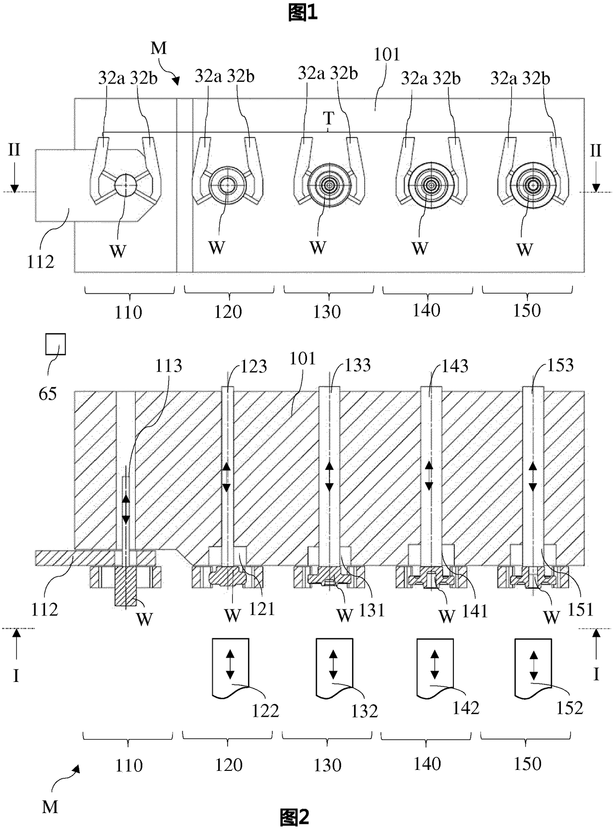
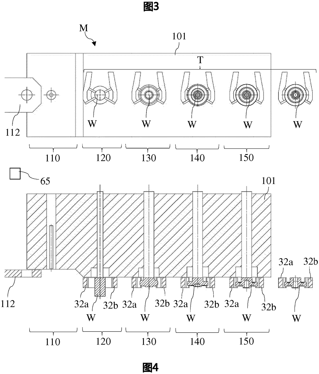
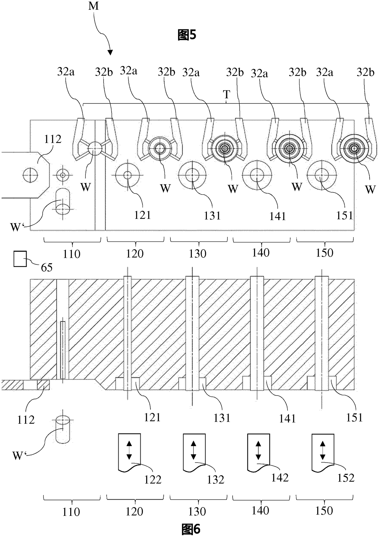
[0041] Figure 1-6 The schematic overview of , using a molding plant as an example, shows the parts of the processing plant of the invention that are relevant for understanding the invention. figure 1 based on figure 2 The line I-I in the front view, while figure 2 for along figure 1 Cross-sectional view of line II-II in. Correspondingly, image 3 and 5 main view, Figure 4 and 6 is the corresponding cross-sectional view.

[00...


PUM


Abstract

The invention relates to a transport method for transferring workpieces between multiple consecutive stages of a processing unit, in particular a shaping unit, wherein each workpiece is transported ina transport cycle from one stage to the respective following stage of the processing unit, simultaneously by means of multiple mutually moveable gripping tools. In the event of a process disturbance,the transport cycle is interrupted and the gripping tools with the workpieces are moved into a waiting position (27), in which the workpieces are outside of the effective region of processing tools of the stages of the processing unit. After the process disturbance has ended, the transport cycle of the workpieces is recommenced. Resultant damages of the process disturbance can be prevented via the movement of the gripping tools into a secure waiting position outside of the effective region of the processing tools of the stages.

Description

technical field [0001] The invention relates to a transport method according to the preamble of claim 1 for transferring workpieces between successive stations of a processing plant, in particular a forming plant, and a preamble according to claim 7 The transport device for carrying out the transport method described in the preamble. Background technique [0002] In solid-state forming as well as other forming or machining processes, workpieces usually pass sequentially through several stations of a processing plant, wherein the workpieces are further transported station by station. In forming equipment, the station is usually a loading station and several different forming stations. For transporting the workpieces from station to station, transport devices are generally used which are usually equipped with pincer-like grippers and operate in the machine cycle of the processing plant, wherein the grippers simultaneously grip the workpieces and transfer the workpieces from o...

Claims


Application Information

Patent Timeline
Patent Type & Authority Applications(China)
IPC IPC(8): B21K27/04B21D43/05B21D43/02
CPCB21D43/025B21D43/05B21D43/10B21K27/04
Inventor 马库斯·莫泽史蒂芬·雷布恩德古特安德烈亚斯·马里茨安德烈亚斯·马特
Owner HATEBUR UMFORMMASCHEN
Learn More