Power interchange control device, power interchange control method, and power interchange control system

A flow control and power technology, applied in the direction of power network operating system integration, circuit devices, information technology support systems, etc., can solve problems such as inability to determine power customers

Active Publication Date: 2018-12-21
MITSUBISHI ELECTRIC CORP
View PDF5 Cites 0 Cited by
  • Summary
  • Abstract
  • Description
  • Claims
  • Application Information

AI Technical Summary

Problems solved by technology

[0007] However, in the power distribution device described in Patent Document 1, there is a problem that the power customer who receives the distribution request calculates the available amount of circulation according to the requ

Method used


Image

  • Power interchange control device, power interchange control method, and power interchange control system
  • Power interchange control device, power interchange control method, and power interchange control system
  • Power interchange control device, power interchange control method, and power interchange control system

Examples


Embodiment approach 1

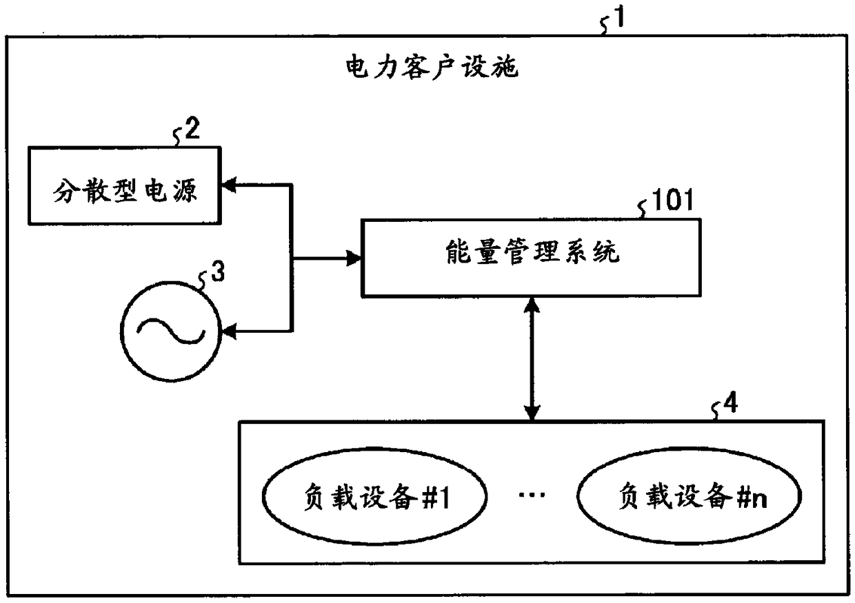
[0055] figure 1 It is a diagram showing a configuration example of a power customer facility among power customers having an energy management system having the function of the power distribution device according to Embodiment 1 of the present invention. The power customer facility 1 includes an energy management system 101 , distributed power sources 2 and load devices 4 . The load device 4 includes a load device #1 to a load device #n. n is an integer of 1 or more. That is, the energy management system 101 of Embodiment 1 is a power flow control device among power customers holding the distributed power source 2 and the load facility 4 .

[0056] The load device 4 and the distributed power source 2 are connected to the power system 3 . The distributed power source 2 includes a power generation facility for generating power, a storage battery for storing and supplying electric power, and an electric vehicle. The power generation facilities include power generation facilit...

Embodiment approach 2

[0097] Next, an energy management system according to Embodiment 2 will be described. In Embodiment 1, when excess electricity or power shortage occurs, the distribution amount is determined among electric power customers, and electric power is distributed. However, depending on how distributed power sources are used by power customers, the meanings of excess power and insufficient power may change. For example, a power customer who owns a storage battery as a distributed power source may purchase all of the power from the power company depending on the time period, and may not use the power stored in the storage battery. In this case, the electric power that can be supplied from the storage battery during this time period can be regarded as the surplus electric power. Alternatively, among electric power customers who own generators as distributed power sources, depending on the time period, they may not be able to meet their own power needs simply by purchasing power from th...

Embodiment approach 3

[0122] Figure 24 It is a figure which shows the structural example of the energy management system 10b which concerns on Embodiment 3 of this invention. Components having the same functions as in Embodiment 2 are assigned the same reference numerals as in Embodiment 2, and redundant descriptions are omitted. Hereinafter, points different from Embodiment 2 will be described.

[0123] The energy management system 101b of Embodiment 3 is the same as the energy management system of Embodiment 2 except having provided the distribution plan preparation part 102b instead of the distribution plan preparation part 102a. The distribution plan preparation unit 102b is the same as the distribution plan preparation unit 102a of the second embodiment except that the distribution cost calculation unit 208 for calculating the distribution cost per distribution request amount is added to the distribution plan preparation unit 102a of the second embodiment.

[0124] Figure 25 It is a flowc...


PUM


Abstract

The present invention is an energy management system (101) for an electric power consumer that maintains a distributed power supply, wherein the power management system (101) is provided with: an interchange request preparation unit (201) for preparing an interchange request that includes an interchange request amount; an interchange requirement determination unit (202) for calculating an interchange requirement on the basis of the interchange request amount; a transceiver (103) for transmitting the interchange request amount and the interchange requirement to another energy management system;an interchange negotiation counterpart determination unit (203) for determining an interchange negotiation counterpart on the basis of the received interchange requirement; an interchange response determination unit (204) for calculating a possible interchange amount for each negotiation counterpart on the basis of the received interchange request amount, and transmitting the possible interchangeamount via the transceiver (103); and an interchange plan determination unit (205) for determining an interchange plan on the basis of the received possible interchange amount and the interchange request amount of the host unit.

Description

technical field [0001] The present invention relates to a power distribution control device, a power distribution control method, and a power distribution control system that control power distribution among a plurality of power customers. Background technique [0002] In recent years, distributed power sources such as power generators using renewable energy such as sunlight and storage batteries have been introduced to power customers, and energy management systems for cooperatively controlling them have been developed. Furthermore, the following technologies are required in the future: not only a single energy management system controls the distributed power sources under its own management, but also cooperation and coordination between energy management systems, and the supply of excess power and Raise such circulating power in case of insufficient power. [0003] For example, in Patent Document 1, an electric power distribution device is proposed. When a plurality of el...

Claims


Application Information

Patent Timeline
IPC IPC(8): H02J3/00G06Q50/06H02J3/38
CPCG06Q50/06H02J3/38H02J3/008Y04S50/10Y04S20/222Y02B70/3225H02J3/322Y04S50/12H02J3/00H02J7/0068
Inventor 西田义人
Owner MITSUBISHI ELECTRIC CORP
Why Eureka
Try Eureka