Stereoscopic imaging method and device based on drone

A stereoscopic imaging and unmanned aerial vehicle technology, applied in stereoscopic systems, image communications, electrical components, etc., can solve the problems of high cost, large distance between binocular cameras, limited application of binocular cameras, etc., and achieve the goal of reducing imaging resolution demand, the effect of improving the accuracy of 3D reconstruction

Inactive Publication Date: 2021-01-26
SZ DJI TECH CO LTD
View PDF6 Cites 0 Cited by
  • Summary
  • Abstract
  • Description
  • Claims
  • Application Information

AI Technical Summary

Problems solved by technology

[0003] The existing technology uses binocular cameras to obtain stereoscopic images. Under the trade-off between image resolution and object distance accuracy, the inevitable result is that the distance between binocular cameras is relatively large
However, due to the limitation of the position of the small UAV, the application of the binocular camera is very limited.
In the industry, large-scale drones are mostly used for related surveying and mapping, which is costly and not conducive to promotion

Method used


Image

  • Stereoscopic imaging method and device based on drone
  • Stereoscopic imaging method and device based on drone
  • Stereoscopic imaging method and device based on drone

Examples


Embodiment 1

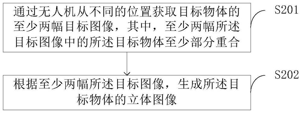
[0028] Embodiment 1 of the present invention provides a stereoscopic imaging method based on a drone. figure 2 It is a flow chart of the stereoscopic imaging method based on the drone provided by the embodiment of the present invention. Such as figure 2 As shown, the stereoscopic imaging method based on unmanned aerial vehicle may comprise the steps:

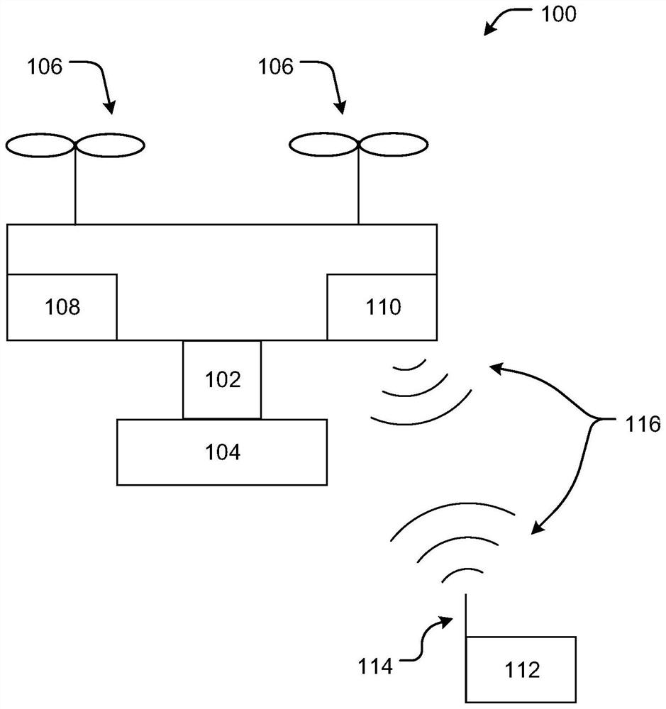
[0029] Step S201: Obtain at least two target images of the target object from different positions by the UAV 100, wherein the target object in the at least two target images at least partially overlap;

[0030] Optionally, the at least two target images may include two or more. Preferably, the drone 100 acquires two target images of the target object from different positions.

[0031] In this embodiment, the UAV 100 acquires two target images of the target object from different positions, and the specific implementation methods may include the following two types:

[0032] The first

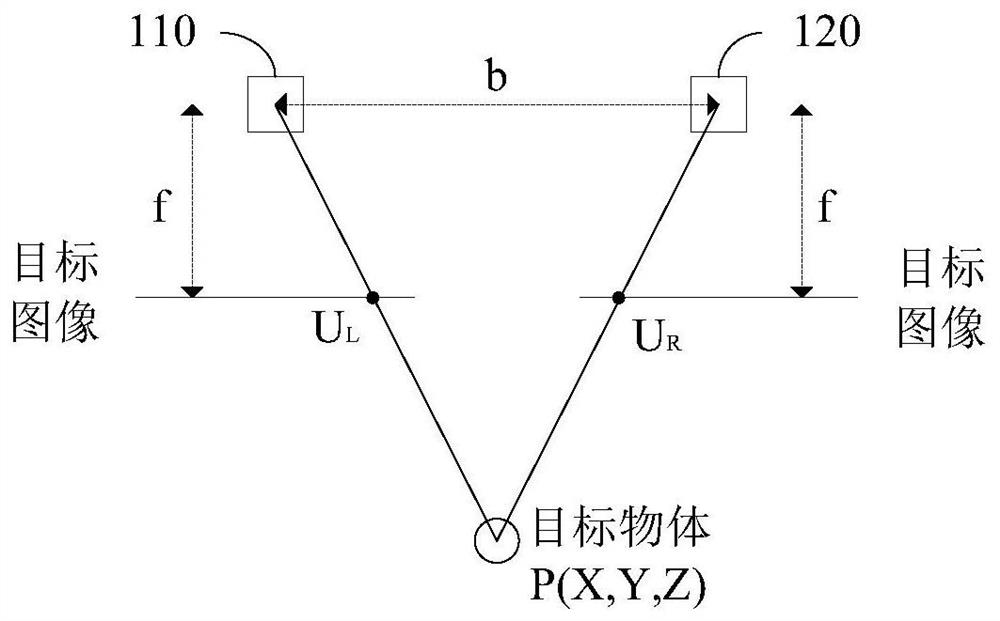
[0033] combine image 3 and Figure 4 ...

Embodiment 2

[0058] combine Figure 6 and Figure 7, Embodiment 2 of the present invention provides a stereoscopic imaging device based on a drone, the device may include a drone 100 and a processor 200 (for example, a single-core or multi-core processor), the processor 200 and the The drone 100 is connected in communication.

[0059] The processor 200 may be a central processing unit (central processing unit, CPU). The processor 200 may further include a hardware chip. The aforementioned hardware chip may be an application-specific integrated circuit (application-specific integrated circuit, ASIC), a programmable logic device (programmable logic device, PLD) or a combination thereof. The above-mentioned PLD may be a complex programmable logic device (complex programmable logic device, CPLD), a field-programmable gate array (field-programmable gate array, FPGA), a general array logic (generic array logic, GAL) or any combination thereof.

[0060] The processor 200 may include one or mo...

Embodiment 3

[0089] Embodiment 3 of the present invention provides a computer-readable storage medium, on which a computer program is stored, and the program is executed by a processor in the steps of the UAV-based stereoscopic imaging method described in Embodiment 1 above.


PUM


Abstract

The present invention provides a UAV-based stereoscopic imaging method and device, the method comprising: acquiring at least two target images of a target object from different positions by a UAV, wherein at least two of the target images are The target objects are at least partially overlapped; and a stereoscopic image of the target object is generated according to at least two of the target images. The two cameras in the binocular camera are replaced by a drone, and at least two target images of the target object are acquired from different positions, thereby obtaining a stereoscopic image of the target object, and the distance between the phase acquisition points is increased in a low-cost manner. The distance reduces the demand for imaging resolution and improves the accuracy of 3D reconstruction.

Description

technical field [0001] The invention relates to the field of imaging, in particular to a stereoscopic imaging method and device based on an unmanned aerial vehicle. Background technique [0002] Stereoscopic vision is achieved through the difference in the position of the phase collection point. For example, there is a certain distance between the left and right eyes of a person, and there are subtle differences between the formed phases, so the distance of the object can be judged. The distance between the phase collection points is called the baseline. The farther the baseline is, the easier it is to obtain stereo vision, or the more obvious the stereo vision obtained. [0003] In the prior art, binocular cameras are used to obtain stereoscopic images. Under the trade-off between image resolution and object distance accuracy, the inevitable result is that the distance between the binocular cameras is relatively large. Due to the limitation of the position of the small UAV...

Claims


Application Information

Patent Timeline
Patent Type & Authority Patents(China)
IPC IPC(8): H04N13/211
CPCH04N13/20H04N13/211H04N13/218
Inventor 周震昊李昊南
Owner SZ DJI TECH CO LTD
Why Eureka
Try Eureka