Rapid edge cutting die switching device and operation method thereof

A trimming die, rapid technology, applied in the direction of metal processing equipment, forming tools, manufacturing tools, etc., can solve problems such as difficult operation and manual operation, and achieve the effects of reducing labor intensity, facilitating replacement operations, and improving the accuracy of replacement and installation

Pending Publication Date: 2018-12-25
GUANGZHOU DEZHI METAL PROD CO LTD
View PDF0 Cites 3 Cited by
  • Summary
  • Abstract
  • Description
  • Claims
  • Application Information

AI Technical Summary

Problems solved by technology

In the process of installing the trimming die, it is a very important link to install the trimming die manually using a crowbar to align the limit on the trimming machine. In this link, because the trimming die is too heavy, manual operation is difficult, and at the same time It is necessary to align the limit holes on the trimming machine, which makes the operation more difficult; usually it takes two people about 4 hours to complete the disassembly and assembly of the trimming die

Method used


Image

  • Rapid edge cutting die switching device and operation method thereof
  • Rapid edge cutting die switching device and operation method thereof
  • Rapid edge cutting die switching device and operation method thereof

Examples


Embodiment 1

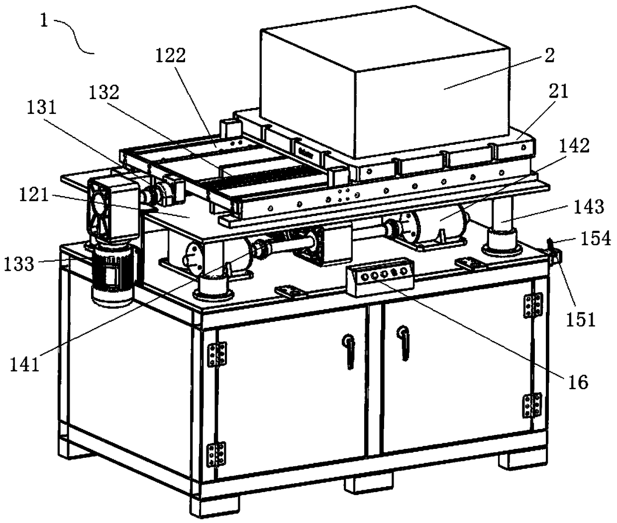
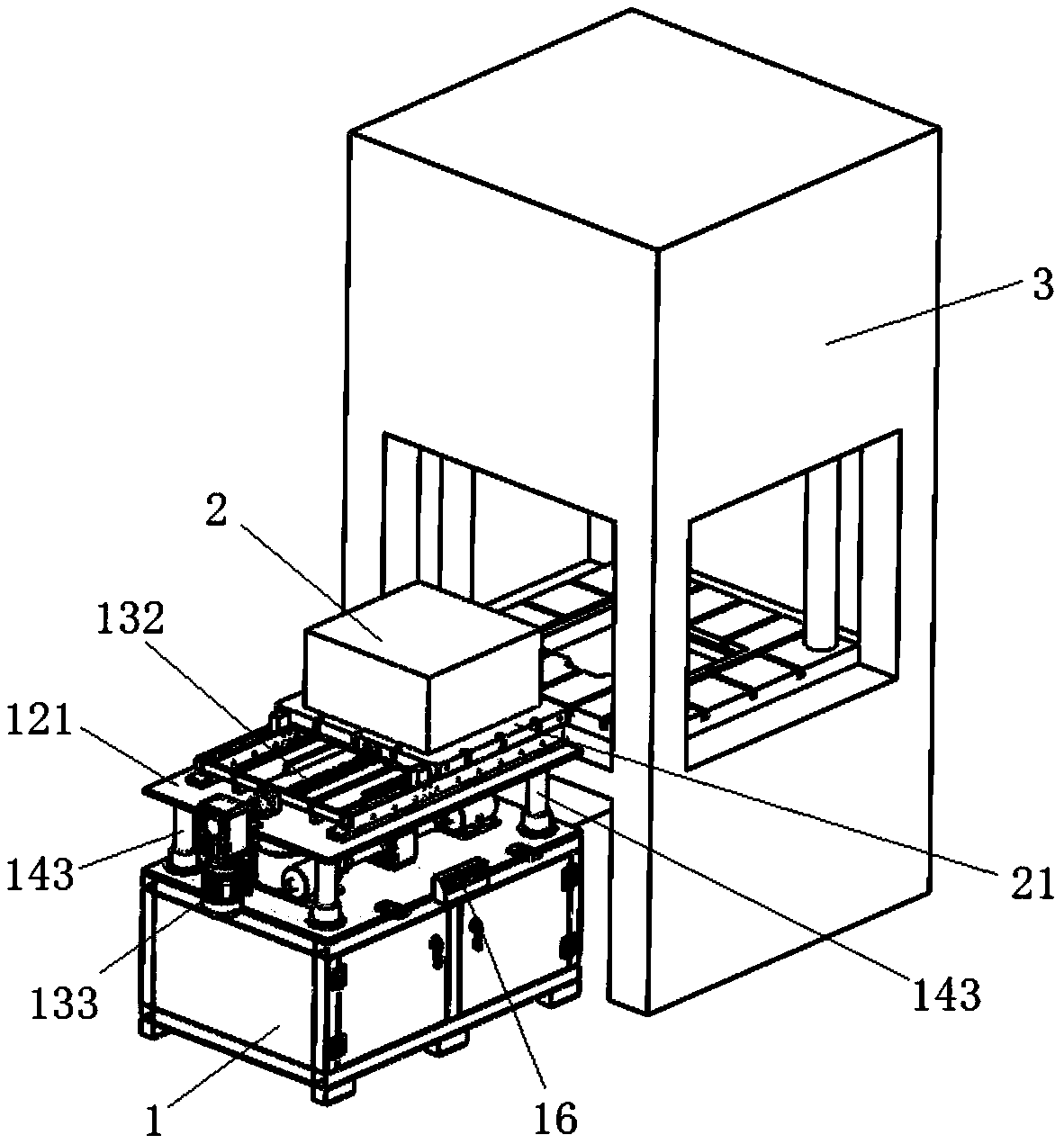
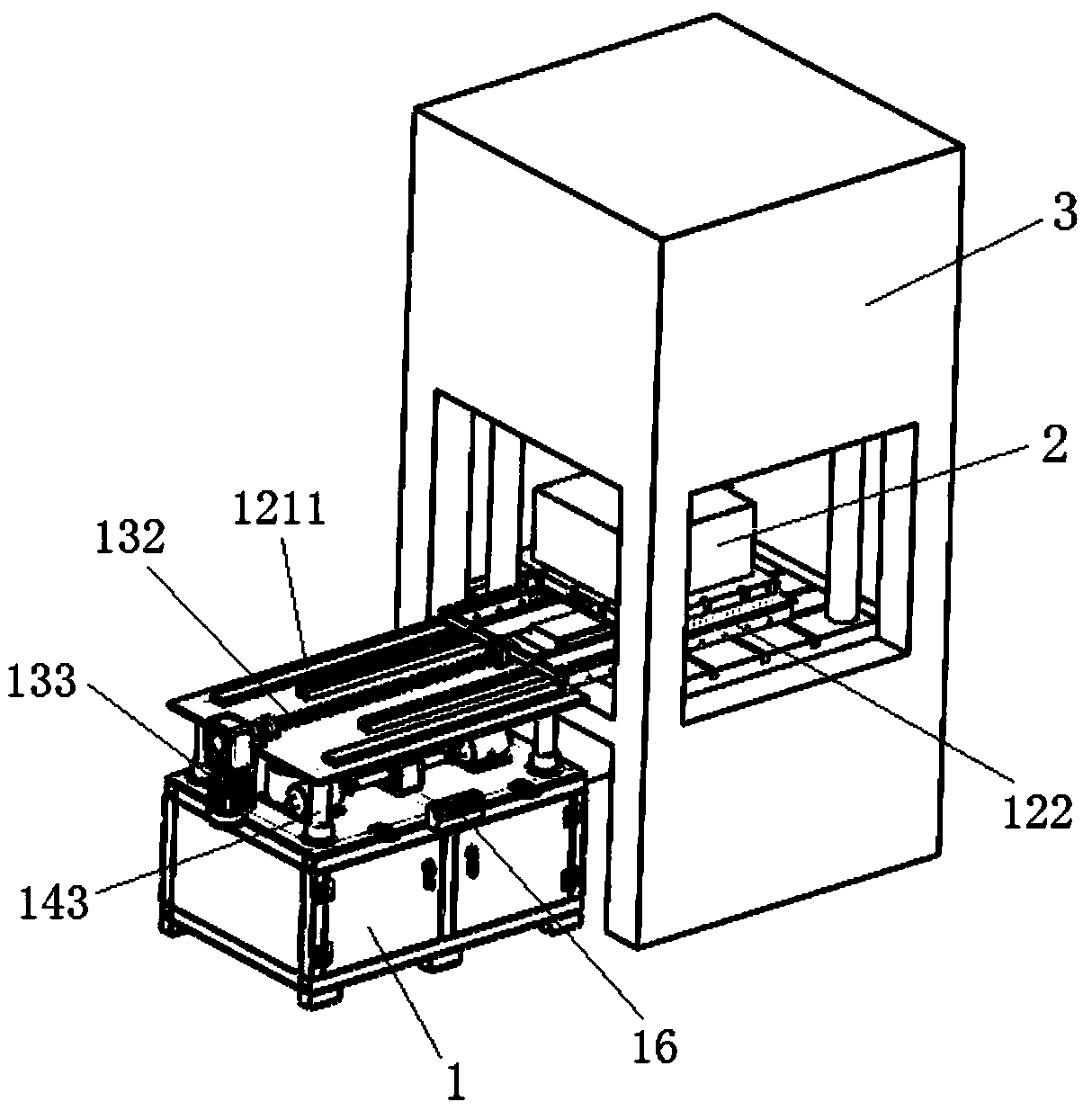
[0041] Such as Figure 1-6 As shown, in the present embodiment, a device for quickly changing the trimming die is provided, including a die changing trolley 1, and the die changing trolley 1 is provided with a common backing plate 21 for carrying the trimming die 2, and A support plate for carrying the common backing plate 21 .

[0042]The common backing plate 21 is set as a rectangular plate, and a central positioning mechanism for positioning the edge trimming die 2 is arranged on the common backing plate 21, so as to facilitate the positioning and installation of the edge trimming dies 2 of different dimensions. As a preferred solution, the central positioning mechanism in this embodiment is a positioning pin hole provided on the bottom surface of the common backing plate 21, and in this embodiment, two positioning pins are provided on the support plate 1221, and protrudingly arranged on the end face of the support plate.

[0043] The supporting board includes a male boar...

Embodiment 2

[0055] The same parts as in Embodiment 1 will not be described in detail. In this embodiment, the first drive device includes a first telescopic cylinder horizontally arranged on the mold changing trolley 1, and the telescopic rod of the first telescopic cylinder The support plate is connected to control the horizontal position of the support plate. In addition, the second driving device includes a second telescopic cylinder vertically arranged on the mold changing trolley 1, and the telescopic rod of the second telescopic cylinder is connected to the support plate, so as to adjust the height of the support plate. adjust.

[0056] The telescopic cylinders in this embodiment all adopt hydraulic or pneumatic telescopic cylinders, and specific structural forms can be referred to the prior art.


PUM


Abstract

The invention discloses a rapid edge cutting die switching device. The device comprises a die switching trolley, wherein a common cushion board for bearing the edge cutting die, and a supporting platefor supporting the common cushion board are arranged on the die switching trolley; the supporting plate comprises a male plate and a female plate which are in sliding interconnection; the female plate in sliding can extend into an edge cutting machine; a first driving device for changing the horizontal position of the common cushion board, and a second driving device for changing the vertical height of the common cushion board are arranged on the die switching trolley. The invention further discloses an operation method for rapidly replacing the edge cutting die. With the adoption of the device and the method, the problem of a traditional mode for manually prizing the edge cutting die to switch is avoided; the die switching efficiency of the edge cutting die is effectively improved, thusthe labor cost is reduced, and the production benefit is increased.

Description

technical field [0001] The invention belongs to the technical field of industrial mold replacement, and in particular relates to a device for quickly replacing a trimming mold and an operation method thereof. Background technique [0002] In the supply chain of automobile production, in order to meet product quality and reduce labor intensity of workers, trimming dies have been used more and more widely. With the diversified and individualized needs of customers, the traditional mass production methods can no longer meet the needs of customers. Small batch, multi-variety production methods are imperative. At the same time, because the structure and configuration of the cars produced will be very different, the switching of molds will become frequent. The mold switching time refers to the time interval between the last qualified product of the previous variety and the first qualified product of the next variety. From a cost point of view, this part of the time is time with...

Claims


Application Information

Patent Timeline
IPC IPC(8): B21D37/14
CPCB21D37/147
Inventor 付红程文浩
Owner GUANGZHOU DEZHI METAL PROD CO LTD
Why Eureka
Try Eureka