
A robotic arm for product transfer

A technology of robotic arms and products, applied in the directions of manipulators, manufacturing tools, chucks, etc., can solve problems such as damage, limited application scope, and weak suction, and achieve the effect of easy adsorption

Active Publication Date: 2021-08-06
山东省金鋆建材有限公司
View PDF7 Cites 0 Cited by
  • Summary
  • Abstract
  • Description
  • Claims
  • Application Information

AI Technical Summary

Problems solved by technology

The mechanical arm with this structure can meet the requirements of various types of circuit board handling by adjusting the position of the air nozzle. However, due to the uneven surface of the circuit board, the grasping method of the suction cup is not firm, and it is very easy during the transfer process. Dropping causes damage to the circuit board, which limits its scope of application

Method used


Image

  • A robotic arm for product transfer
  • A robotic arm for product transfer
  • A robotic arm for product transfer

Examples


Embodiment 1

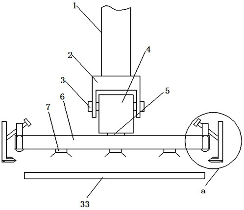
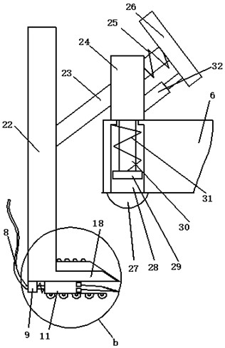
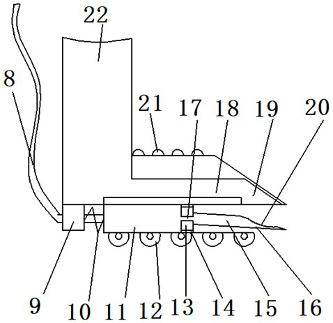
[0021] refer to Figure 1-4, a specific embodiment of the present invention includes a mechanical arm body 1, a first connecting block 4 is movably connected to the lower part of the mechanical arm body 1 through a first connecting arm 2 and a rotating shaft 3, and the lower part of the first connecting block 4 is connected through a rotating shaft 5 A support plate 6 is movably connected, and several suction cups 7 are fixedly connected to the bottom of the support plate 6. The two sides of the support plate 6 are respectively connected with a second fixed block 24, and a first connecting rod is movably inserted on the second fixed block 24. 23. The angle between the first connecting rod 23 and the second fixing block 24 is 45°, the inner side of the first connecting rod 23 is fixedly connected with the third fixing block 26, and the third fixing block 26 and the second fixing block 24 A cylinder 32 and a second spring 25 are connected between them. The second spring 25 is sl...

Embodiment 2

[0024] In this embodiment, on the basis of Embodiment 1, further improvements are made to the grasping part and the first cushion.

[0025] refer to Figure 5-6 , the gripping plate 18 and the wedge portion 19 are in sliding contact through a stepped contact surface 36, the top of the stepped contact surface 36 is provided with a second airbag 37, and the bottom of the second airbag 37 communicates with the casing 11 through a connecting hole 38, A fourth spring 39 is provided at the bottom of the stepped contact surface 36 . The third cushion 34 is provided with a cavity 40 , and the top of the cavity 40 is provided with a first elastic piece 41 , and the top of the second airbag 37 communicates with the cavity 40 . In the process of grabbing the circuit board, after the compressed air is fed into the air pipe 8, the compressed air enters the second air bag 37 through the connecting hole 38, so that the grabbing plate 18 is separated from the wedge-shaped part 19, so that th...


PUM


Abstract

The invention discloses a mechanical arm for product transfer, comprising a mechanical arm body, a first connecting arm, a rotating shaft, a first connecting block, a rotating shaft, a support plate, a suction cup, a second fixed block, and the second fixed block is movable The first connecting rod is inserted, the inner side of the first connecting rod is fixedly connected with the third fixed block, the cylinder and the second spring are connected between the third fixed block and the second fixed block, and the outer side of the first connecting rod is connected with the second fixed block. Two connecting arms, the bottom of the second connecting arm is connected with grabbing plate, wedge-shaped part, first fixed block, slide rail, sleeve pipe, air pipe, first spring, runner, the inside of sleeve pipe is connected with piston, the outside of piston A hard tube is fixedly connected, a wedge-shaped tube is connected to the outside of the hard tube, and an air bag is connected above the wedge-shaped tube, and the hard tube and the sleeve tube are connected to each other through the first through hole. The invention can improve the deficiencies of the prior art, and can have a better grasping effect for circuit boards with uneven surfaces.

Description

technical field [0001] The invention relates to a mechanical arm device, in particular to a mechanical arm used for product transfer. Background technique [0002] A robotic arm is an automatic operating device that can imitate certain movement functions of the human hand and arm to grab, carry objects or operate tools according to a fixed program. The feature is that various expected operations can be completed through programming, and the structure and performance have both the advantages of man and robot. Chinese invention patent CN 205201544 U discloses a transfer robot arm for flexible circuit boards. The mechanical arm with this structure can meet the requirements of various types of circuit board handling by adjusting the position of the air nozzle. However, due to the uneven surface of the circuit board, the grasping method of the suction cup is not firm, and it is very easy during the transfer process. Dropping causes damage to the circuit board, thereby limiting ...

Claims


Application Information

Patent Timeline
Patent Type & Authority Patents(China)
IPC IPC(8): B25J15/06
CPCB25J15/0683
Inventor 梁显梅
Owner 山东省金鋆建材有限公司
Learn More