Steel-wire-rope-driven folding joint template for assembly-type building and construction method thereof

A wire rope and prefabricated technology, which is applied to the foldable seam formwork driven by steel wire rope for prefabricated buildings and the construction field, which can solve the problems of low formwork strength, unstable fixation, and high labor intensity.

Pending Publication Date: 2018-12-25
NORTH CHINA UNIV OF WATER RESOURCES & ELECTRIC POWER
View PDF0 Cites 2 Cited by
  • Summary
  • Abstract
  • Description
  • Claims
  • Application Information

AI Technical Summary

Problems solved by technology

[0002] Prefabricated buildings refer to buildings assembled on the site with prefabricated walls, floors and other structural parts. The joints between the prefabricated walls need to be connected and fixed by concrete pouring, and formwork is required for concrete pouring. , the traditional formwork mostly uses wood for simple manual fixing and splicing, which is used to fix on both sides of the steel cage in the joint between prefabricated walls, and then poured

Method used


Image

  • Steel-wire-rope-driven folding joint template for assembly-type building and construction method thereof
  • Steel-wire-rope-driven folding joint template for assembly-type building and construction method thereof
  • Steel-wire-rope-driven folding joint template for assembly-type building and construction method thereof

Examples


Embodiment example 1

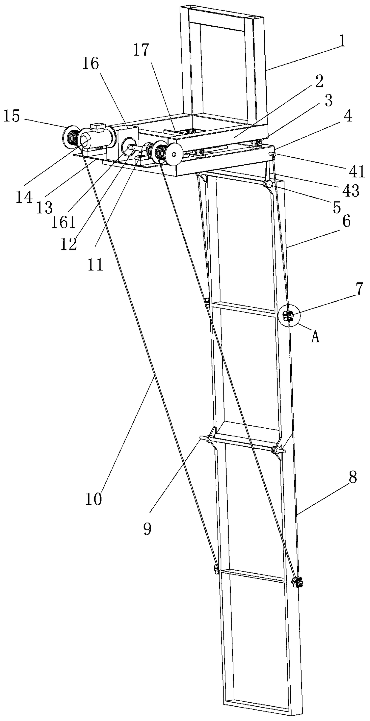
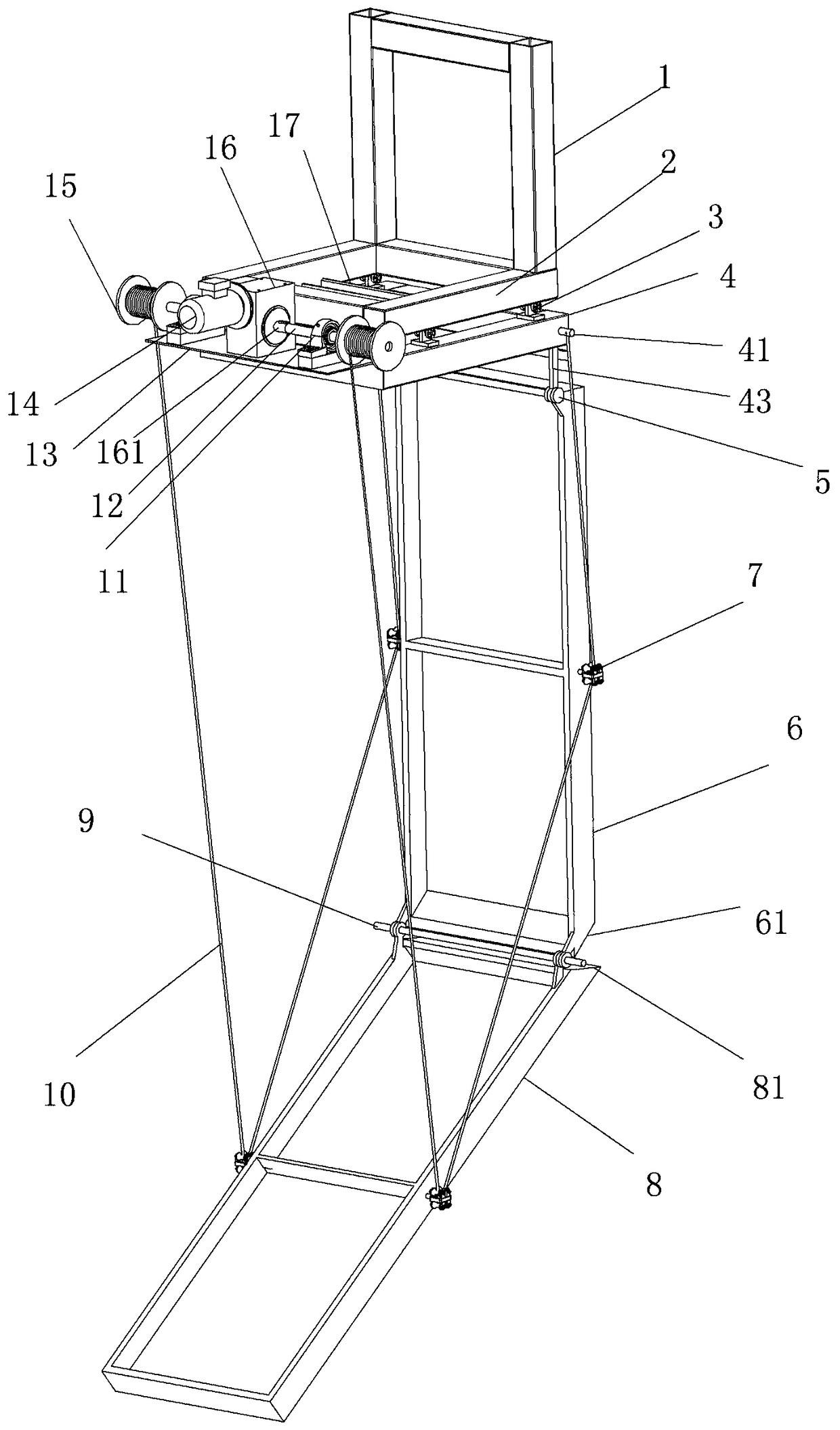
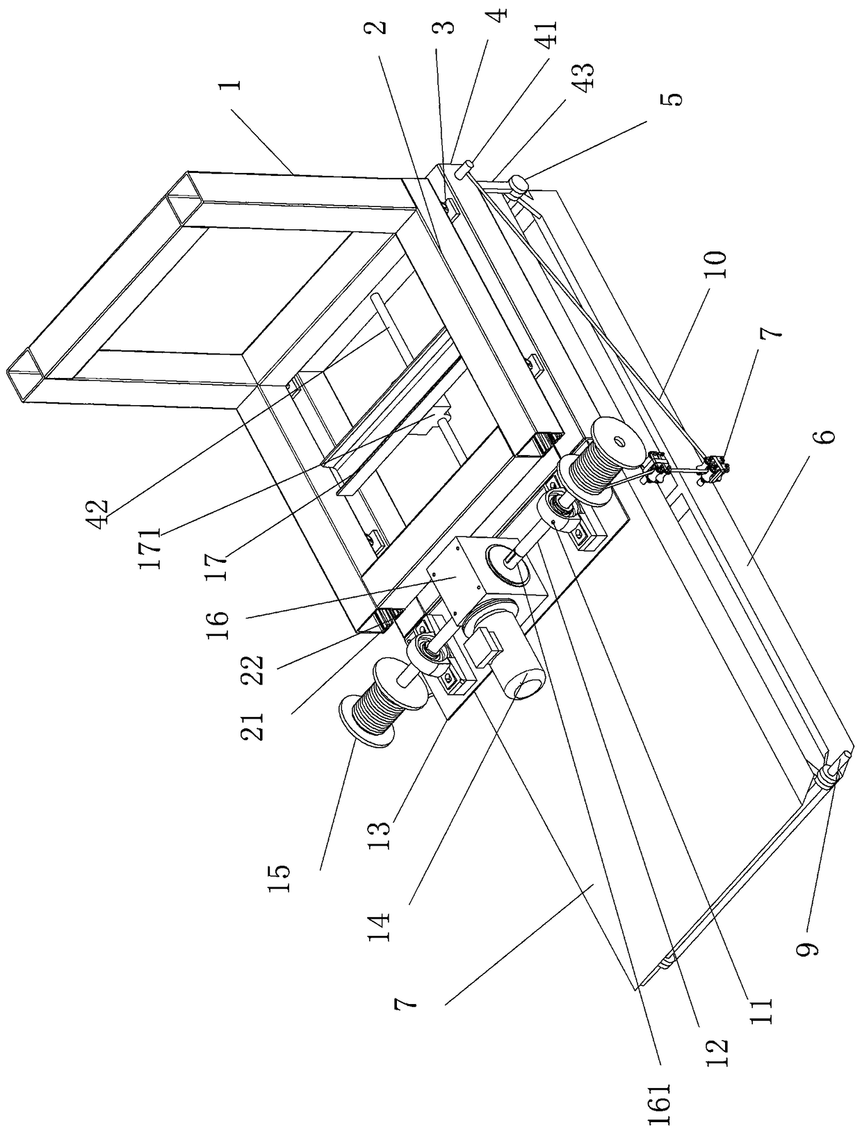
[0035] see Figure 1-9 , a foldable seam formwork driven by wire ropes for prefabricated buildings, the foldable formwork includes a support component, a drive component, and a foldable formwork;

[0036] The support assembly includes a fixed frame and a sliding frame. The sliding frame is installed under the fixed frame through a pulley assembly. The fixed frame includes a horizontal frame and a vertical frame. The vertical frame is installed on the truss of the temporary construction platform through U-shaped mounting bolts and positioning holes. Above, the side structure of the horizontal frame is two relatively parallel square steel pipes. The bottom surface of each square steel pipe is provided with a slit along the length direction of the square steel pipe. a pulley track for use with the pulley assembly;

[0037] Each of the pulley assemblies includes a pulley frame and a pulley. The pulley frame includes a flat plate and a connecting plate fixed vertically to each other...

Embodiment example 2

[0047] see Figure 1-9 , a method of applying the foldable joint formwork described in Implementation Case 1 to carry out the joint construction method of a prefabricated building wall, the specific steps are as follows:

[0048] ① Use the folded templates in pairs, and install them symmetrically on the trusses of the temporary construction platform on both sides of the joints between the prefabricated walls in the prefabricated building through the fixing frame;

[0049] ②The hoisting motor in the driving device drives the wire rope drum to rotate, and the rotating wire rope drum releases the wire rope coiled on the wire rope drum, and the upper formwork and the lower formwork are gradually unfolded downward under the action of their own gravity until When the upper formwork and the lower formwork are fully deployed on the same plane and the steel wire rope is in a slack state, stop releasing the steel wire rope;

[0050] ③The horizontal drive motor on the horizontal frame o...


PUM


Abstract

The invention relates to a steel-wire-rope-driven folding joint template for an assembly-type building and a construction method thereof. The template comprises a fixed frame composed of a horizontalframe and a vertical frame, a pulley track is arranged on the horizontal frame, and a sliding frame is cooperatively connected with the pulley track on the horizontal frame of the fixed frame by meansof a pulley on a pulley assembly. The sliding frame can slide relative to the horizontal frame of the fixed frame, and the bottom of the sliding frame is hinged to two templates in sequence, a steelwire rope penetrates through a rope winding device installed on the sides of the two templates, and a lifting motor installed on the end face of the sliding frame drives a wire rope reel to hoist thesteel wire rope so as to achieve the folding and unfolding of the templates. The foldable templates are used in pairs and are installed on the two sides of each joint between prefabricated walls of the assembly-type building through the fixed frame, the lifting motor drives the wire rope reel to release the steel wire rope, the templates are unfolded sequentially in the vertical direction under the action of the self-gravity, and the relative position of the sliding frame is then adjusted, so that the unfolded templates are in reasonable positions relative to the to-be-poured joints.

Description

technical field [0001] The invention relates to the technical field of construction machinery and equipment, in particular to a foldable seam formwork driven by a steel wire rope for an assembled building and a construction method. Background technique [0002] Prefabricated buildings refer to buildings assembled on the site with prefabricated walls, floors and other structural parts. The joints between the prefabricated walls need to be connected and fixed by concrete pouring, and formwork is required for concrete pouring. , the traditional formwork mostly uses wood for simple manual fixing and splicing, which is used to fix on both sides of the steel cage in the joint between prefabricated walls, and then poured into concrete, because the strength of the formwork is not high, and the fixation is not firm , the fixing process and the dismantling process are quite cumbersome, and the joints between each prefabricated wall need to be re-fixed with the formwork. Low, labor-in...

Claims


Application Information

Patent Timeline
IPC IPC(8): E04G9/08E04G13/00
CPCE04G9/083E04G13/00
Inventor 上官林建赵顺波金向杰杨亚彬李刚运红丽
Owner NORTH CHINA UNIV OF WATER RESOURCES & ELECTRIC POWER
Why Eureka
Try Eureka