Internal combustion engine exhaust pipe flow-aiding ring

A technology for exhaust pipes and internal combustion engines, which is applied in exhaust treatment, exhaust devices, mechanical equipment, etc., can solve problems such as complex structures and inconspicuous acceleration effects, and achieve improved flow rate, reduced accumulation, and faster exhaust. speed effect

Active Publication Date: 2018-12-25
全椒县全动机械有限公司
View PDF7 Cites 2 Cited by
  • Summary
  • Abstract
  • Description
  • Claims
  • Application Information

AI Technical Summary

Problems solved by technology

However, the existing gas acceleration device still has the problems of inconspicuous acceleration effect and complex structure.

Method used


Image

  • Internal combustion engine exhaust pipe flow-aiding ring
  • Internal combustion engine exhaust pipe flow-aiding ring

Examples


Embodiment Construction

[0015] The following will clearly and completely describe the technical solutions in the embodiments of the present invention with reference to the accompanying drawings in the embodiments of the present invention. Obviously, the described embodiments are only some, not all, embodiments of the present invention. Based on the embodiments of the present invention, all other embodiments obtained by persons of ordinary skill in the art without making creative efforts belong to the protection scope of the present invention.

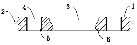
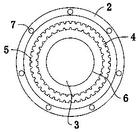
[0016] see Figure 1-2 , an internal combustion engine exhaust pipe flow aid ring, including a flow aid ring body 1, a protruding ring 2 is arranged on the outside of the flow aid ring body 1, and mounting holes 7 are evenly distributed on the protruding ring 2, and the The inside of the flow aid ring body 1 is provided with a first channel 3 and a second channel 4, the first channel 3 is located inside the second channel 4, and the inner wall of the first cha...


PUM


Abstract

The invention discloses an internal combustion engine exhaust pipe flow-aiding ring. The internal combustion engine exhaust pipe flow-aiding ring comprises a flow-aiding ring body, and a protruding ring is arranged on the outer side of the flow-aiding ring body. Mounting holes are evenly formed in the protruding ring, and the flow-aiding ring body is internally provided with a first channel and asecond channel. The first channel is located on the inner side of the second channel, and a streamlined flow-aiding protrusion structure is arranged on the inner wall of the first channel. Flow guiding grooves are evenly formed in the inner wall of the second channel. The internal combustion engine exhaust pipe flow-aiding ring has a reasonable design and a simple structure, the first channel andthe second channel are arranged, the streamlined flow-aiding protrusion structure disposed in the first channel is in the shape of a water drop, and the streamlined flow-aiding protrusion structure inthe shape of the water drop reduces the resistance of gas, accelerates the gas exhaust rate, reduces accumulation of carbon depositing in an internal combustion engine, and prolongs the service lifeof the internal combustion engine.

Description

technical field [0001] The invention relates to the technical field of flow aid rings for exhaust pipes of internal combustion engines, in particular to a flow aid ring for exhaust pipes of internal combustion engines. Background technique [0002] The internal combustion engine is a kind of power machinery, which is a heat engine that directly converts the heat energy released into power by burning fuel inside the machine. When the speed of the internal combustion engine is higher, the amount of air that needs to be discharged from the cylinder per unit time is more. In order to enable the internal combustion engine to have a better discharge smooth effect when the engine rotates at a high speed. A gas acceleration device is usually installed in the exhaust pipe of the internal combustion engine to ensure that the gas will not stay in the front end of the internal combustion engine and in the exhaust pipe. Make the fuel burn more thoroughly and increase the output power o...

Claims


Application Information

Patent Timeline
Patent Type & Authority Applications(China)
IPC IPC(8): F01N13/08
CPCF01N13/08F01N2260/06
Inventor 尤建国
Owner 全椒县全动机械有限公司
Why Eureka
Try Eureka