Clean room affected area detection method

A detection method and clean room technology, applied in separation methods, chemical instruments and methods, measuring devices, etc., can solve problems such as inaccurate monitoring, high cost, and limited pipeline length, so as to improve detection efficiency and reduce monitoring costs , to achieve the effect of accuracy

Active Publication Date: 2018-12-25
L&K ENG SUZHOU
View PDF24 Cites 5 Cited by
  • Summary
  • Abstract
  • Description
  • Claims
  • Application Information

AI Technical Summary

Problems solved by technology

[0004] However, the above method has the following defects: firstly, limited by the length of the pipeline, it is impossible to achieve full coverage of the sampling points for a large-area clean room, and it is impossible to achieve comprehensive monitoring; secondly, because each analysis device is connected to multiple different At the sampling point, there will be residual gas flow from the previous analysis in the analysis equipment, which cannot guarantee the purity of the analysis gas in the subsequent analysis, and the monitoring is inaccurate; again, since the pipelines that can be connected to each analysis equipment are limited, the connected sampling points It is also limited, and needs to be equipped with multiple analytical equipment, which are expensive and costly
To sum up, it is difficult to achieve comprehensiveness and accuracy of monitoring with the method of point monitoring, and the cost is high

Method used


Image

  • Clean room affected area detection method
  • Clean room affected area detection method
  • Clean room affected area detection method

Examples


Embodiment 1

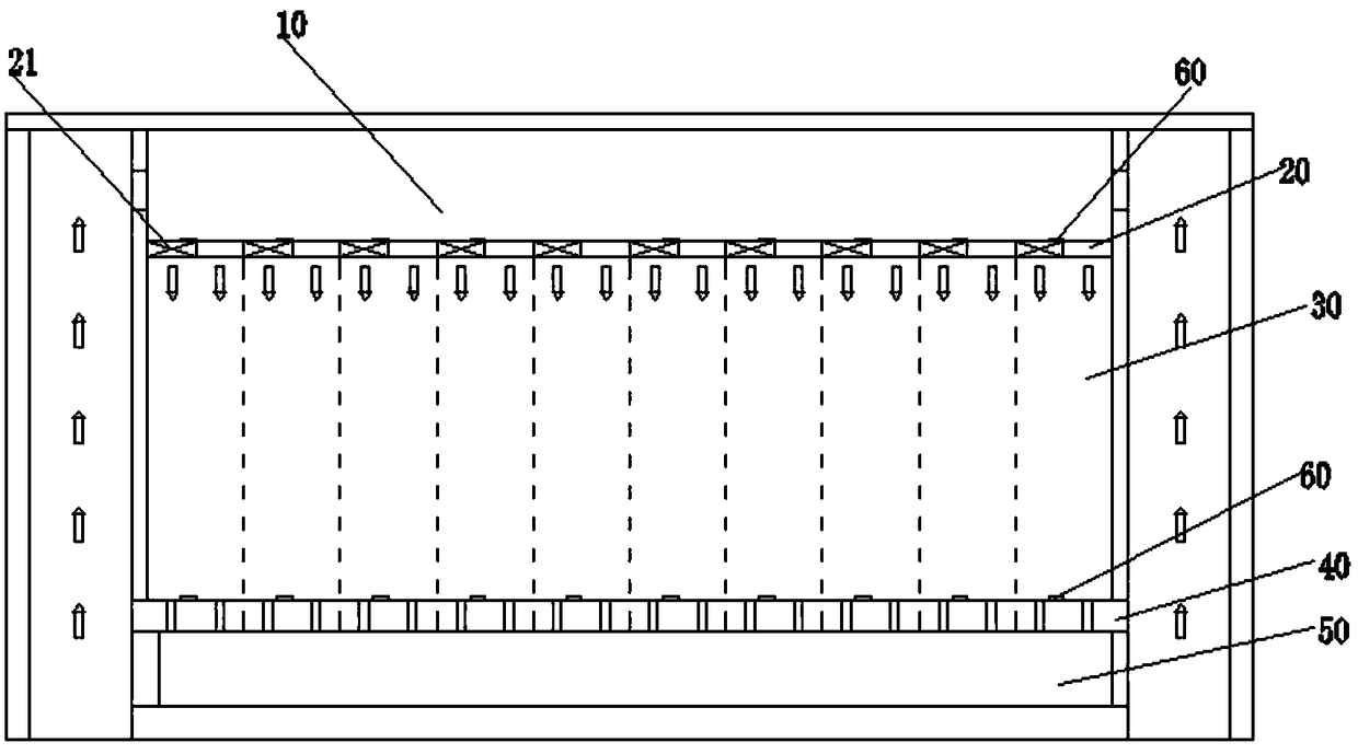
[0031] see figure 1 , as shown in the legend, a method for detecting the damaged area in a clean room, including the following steps:

[0032] (1) Provide a clean room. The clean room includes air supply space 10, ceiling 20, clean space 30, elevated floor 40 and air return space 50 arranged in sequence from top to bottom. The ceiling 20 is divided into a plurality of air supply areas, and the elevated The floor 40 is divided into a plurality of exhaust areas, the air supply area and the exhaust area are arranged one by one up and down, and a cylindrical space is formed between the corresponding two. The clean room also includes a detection mechanism corresponding to the cylindrical space, Each detection mechanism includes a corrosion test piece 60 in contact with the corrosive gas flowing through its corresponding cylindrical space and a detection unit for detecting the electrical performance parameters of the corrosion test piece 60;

[0033] (2) Monitor the electrical perf...

Embodiment 2

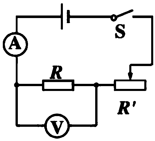
[0047] The rest is the same as the first embodiment, except that the corrosion test piece 60 and the detection unit form a voltammetry resistance circuit, and the corrosion test piece 60 is used as the resistance to be measured in the voltammetry resistance circuit. principle such as image 3 shown.

[0048] Voltammetric resistance measurement is a common method of directly measuring the resistance to be measured by using an ammeter and a voltmeter. The resistance value is measured by using Ohm's law of a part of the circuit: R=U / I. Use an ammeter to measure the current passing through the unknown resistance at this voltage, and then calculate the resistance value of the unknown resistance, which can be roughly divided into two types, the ammeter is internally connected and the ammeter is externally connected. The so-called external internal connection means that the ammeter is connected outside the voltmeter. or inside, the specific steps are as follows:

[0049] (1) Adjust...

Embodiment 3

[0054] The rest are the same as any one of Embodiment 1 or 2, except that the detection unit is an ohmmeter or a multimeter.


PUM


Abstract

The invention discloses a clean room affected area detection method. The method comprises the following steps: (1) providing a clean room, wherein the clean room comprises an air supply space, a ceiling, a cleaning space, a raised floor and an air return space orderly arranged from top to bottom, the ceiling is divided into a plurality of air supply areas, the raised floor is divided into a plurality of air exhaust areas, the air supply areas and the air exhaust areas are arranged up and down in one-to-one correspondence and a cylindrical space is formed between the corresponding air supply area and air exhaust area, the clean room further comprises detection mechanisms in one-to-one correspondence with the cylindrical spaces, and the detection mechanism comprises a corrosion test piece and a detection unit; (2) monitoring an electrical performance parameter of the corrosion test piece of each detection mechanism, and if the electrical performance parameter of the corrosion test pieceof a certain detection mechanism varies continuously according to one trend, judging that the cylindrical space corresponding to the detection mechanism is the affected area. The clean room affected area detection method provided by the invention can realize comprehensiveness and accuracy of corrosive gas detection and can save cost.

Description

technical field [0001] The invention relates to the field of clean production, in particular to a detection method for a clean room damaged area. Background technique [0002] Clean room refers to a well-sealed space that controls air cleanliness, temperature, humidity, pressure, noise and other parameters as required. The development of clean rooms is closely related to modern industry and cutting-edge technology. Due to the environmental requirements of the precision machinery industry (such as gyroscopes, miniature bearings, etc.), the semiconductor industry (such as large-scale integrated circuit production), the development of clean room technology has been promoted. According to domestic statistics, the pass rate of MOS circuit dies produced in an environment without cleanliness requirements is only 10% to 15%, and 64% for memory is only 2%. At present, it is quite common to apply clean rooms in industries such as precision machinery, semiconductors, aerospace, and at...

Claims


Application Information

Patent Timeline
Patent Type & Authority Applications(China)
IPC IPC(8): G01N27/12E04H1/12
CPCE04H1/1277G01N27/12G01N17/002G01N17/04G01R17/105G01R27/02B01D46/42B01D53/38B01D2258/06B01D2279/51F24F3/167G01N33/0027
Inventor 杨政谕
Owner L&K ENG SUZHOU
Why Eureka
Try Eureka