A microstrip bandpass filter

A band-pass filter and filter technology, applied in the field of filters, can solve the problems of large filter volume, unfavorable integration, affecting filter suppression, etc., and achieve low insertion loss, miniaturization, and large out-of-band suppression. Effect

Active Publication Date: 2018-12-25
SHENZHEN SAMSUNG COMM TECH RES +1
View PDF9 Cites 5 Cited by
  • Summary
  • Abstract
  • Description
  • Claims
  • Application Information

AI Technical Summary

Problems solved by technology

Although band-pass filters with cross-coupling structures have been proposed and can also exhibit good performance, most of these band-pass filters use half-wavelength resonator structures, resulting in excessive filter volume, which is not conducive to integration, and is not Ability to flexibly choose where to provide the transmission zero, thereby affecting the rejection of the filter

Method used


Image

  • A microstrip bandpass filter
  • A microstrip bandpass filter
  • A microstrip bandpass filter

Examples


Embodiment 1

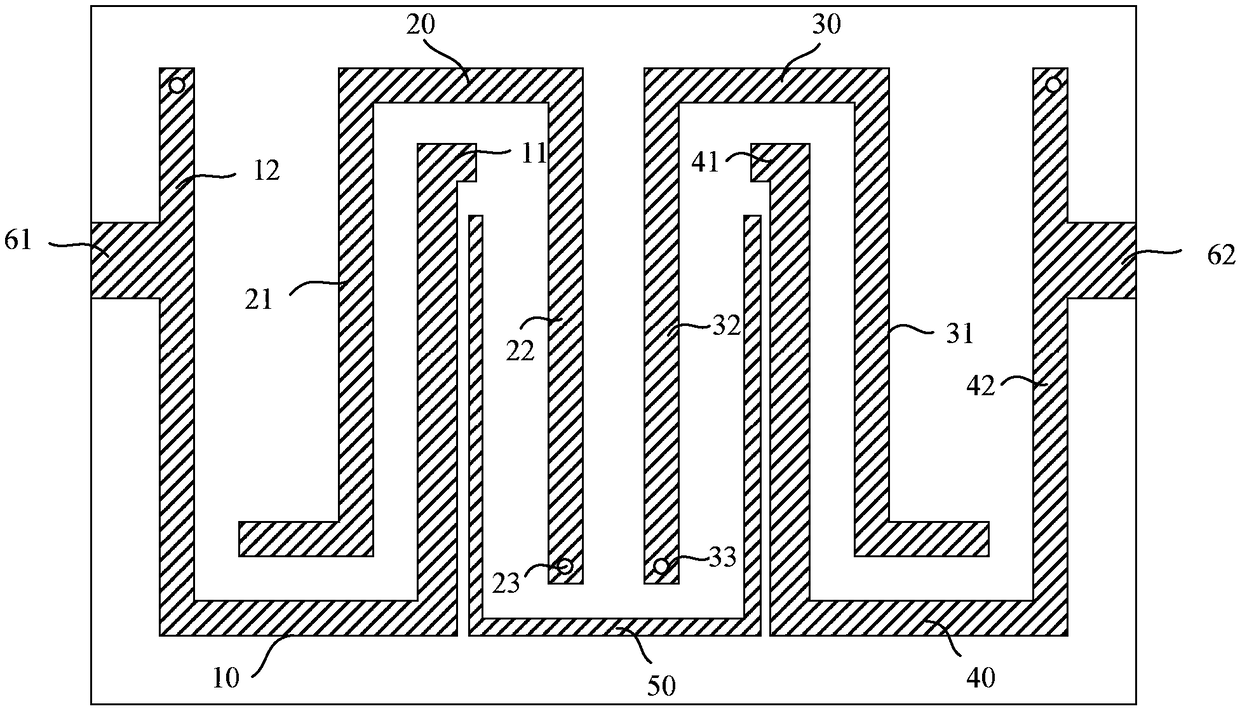
[0058] figure 1 A schematic structural diagram of the first embodiment of the present invention is presented in figure 1 As shown, the opening directions of the first resonance unit 10 and the fourth resonance unit 20 are the same; the opening directions of the second resonance unit 20 and the third resonance unit 30 are the same and opposite to the opening direction of the first resonance unit 10 .

[0059] The short-circuit point 23 of the second resonance arm 22 of the second resonance unit 20 is adjacent to the short-circuit point 33 of the second resonance arm 32 of the third resonance unit 30 .

[0060] Wherein, both ends of the cross-coupled microstrip line 50 are respectively coupled with the first resonance unit 10 and the fourth resonance unit 40, and both ends of the cross-coupled microstrip line 50 are open circuits, so as to generate two Transmit zero.

[0061] Specifically, both ends of the cross-coupled microstrip line 50 are respectively coupled with the firs...

Embodiment 2

[0064] Figure 4 A schematic structural diagram of a second embodiment of the present invention is presented in Figure 4 As shown, the opening directions of the first resonance unit 10 and the third resonance unit 30 are the same; the opening directions of the second resonance unit 20 and the fourth resonance unit 20 are the same and opposite to the opening direction of the first resonance unit 10 .

[0065] The short-circuit point 23 of the second resonance arm 22 of the second resonance unit 20 and the short-circuit point 33 of the second resonance arm 32 of the third resonance unit 30 are away from each other.

[0066] The two ends of the cross-coupled microstrip line 50 are respectively coupled with the first resonance unit 10 and the third resonance unit 30, and both ends of the cross-coupled microstrip line 50 are open circuits to generate two transmission zeros at low frequencies.

[0067] Specifically, both ends of the cross-coupled microstrip line 50 are respectivel...

Embodiment 3

[0070] Figure 7 A schematic structural diagram of a second embodiment of the present invention is presented in Figure 7 As shown, the opening directions of the first resonance unit 10 and the third resonance unit 30 are the same; the opening directions of the second resonance unit 20 and the fourth resonance unit 20 are the same and opposite to the opening direction of the first resonance unit 10 .

[0071] The short-circuit point 23 of the second resonance arm 22 of the second resonance unit 20 and the short-circuit point 33 of the second resonance arm 32 of the third resonance unit 30 are away from each other.

[0072] Wherein, both ends of the cross-coupled microstrip line 50 are respectively coupled with the second resonance unit 20 and the fourth resonance unit 40, and both ends of the cross-coupled microstrip line 50 are short-circuited to generate two transmission zeros at high frequencies .

[0073] Specifically, both ends of the cross-coupled microstrip line 50 ar...


PUM


Abstract

The invention discloses a microstrip band-pass filter, comprising: a resonant unit, wherein the resonant unit comprises a first resonant unit, a second resonant unit, a third resonant unit and a fourth resonant unit arranged in sequence; each resonant unit has a length of a quarter wavelength, and two adjacent resonant units are coupled to each other; and a cross-coupled microstrip line having twoends coupled to two non-adjacent resonant elements, respectively, to produce two transmission zeros at a high frequency and / or a low frequency. The invention aims at providing a microstrip bandpass filter, which can generate two transmission zeros at arbitrary positions through flexibly arranged cross-coupling lines, thereby improving the suppression degree of the filter, and realizing the miniaturization of the microstrip bandpass filter by providing a resonant unit of a quarter wavelength.

Description

technical field [0001] The invention relates to the field of filters, in particular to a microstrip bandpass filter. Background technique [0002] Microwave filter is an indispensable part of modern microwave relay communication, satellite communication, wireless communication and electronic countermeasures and other systems, and it is also the most important and most technical microwave passive device. Among them, the band-pass filter is one of the most important components in the circuit system, and its performance determines the working quality of the system to a large extent. Band-pass filters mainly work in the radio frequency front-end of communication systems, and are used to pass useful signals in a certain frequency range with low loss, while attenuating frequency components in other frequency ranges to a very low level. [0003] However, with the rapid development of modern communication requirements, the available spectrum resources are increasingly tight, so the...

Claims


Application Information

Patent Timeline
Patent Type & Authority Applications(China)
IPC IPC(8): H01P1/203
CPCH01P1/20372
Inventor 李钦陈耀
Owner SHENZHEN SAMSUNG COMM TECH RES
Why Eureka
Try Eureka