
A method of guaranteeing port standing wave performance

A standing wave and performance technology, applied in the field of ensuring port standing wave performance, can solve problems such as the amount of solder paste coating, the coating uniformity of the coating area, the difficulty in precise control, the decline in port standing wave performance, and the difficulty in achieving design performance.

Active Publication Date: 2018-12-25
LEIHUA ELECTRONICS TECH RES INST AVIATION IND OF CHINA
View PDF1 Cites 1 Cited by
  • Summary
  • Abstract
  • Description
  • Claims
  • Application Information

AI Technical Summary

Problems solved by technology

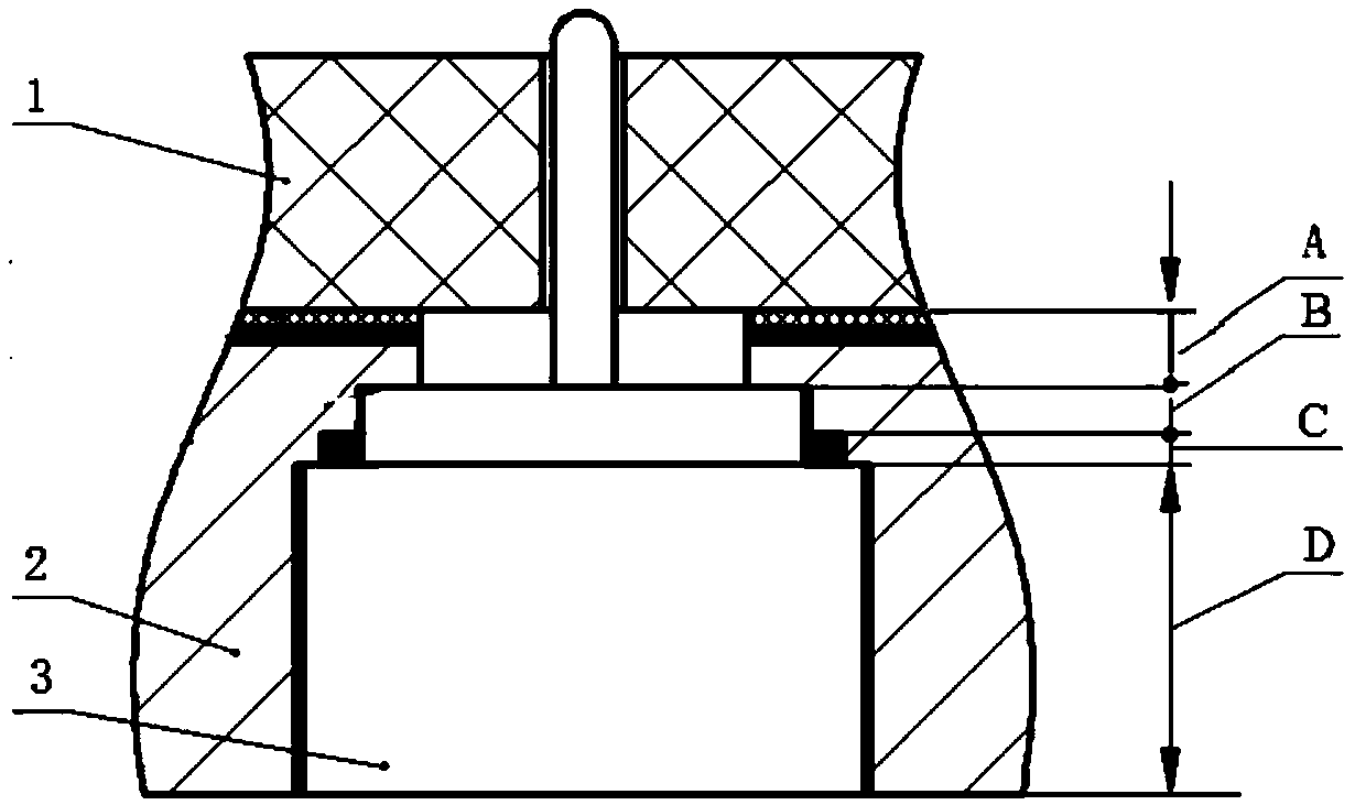
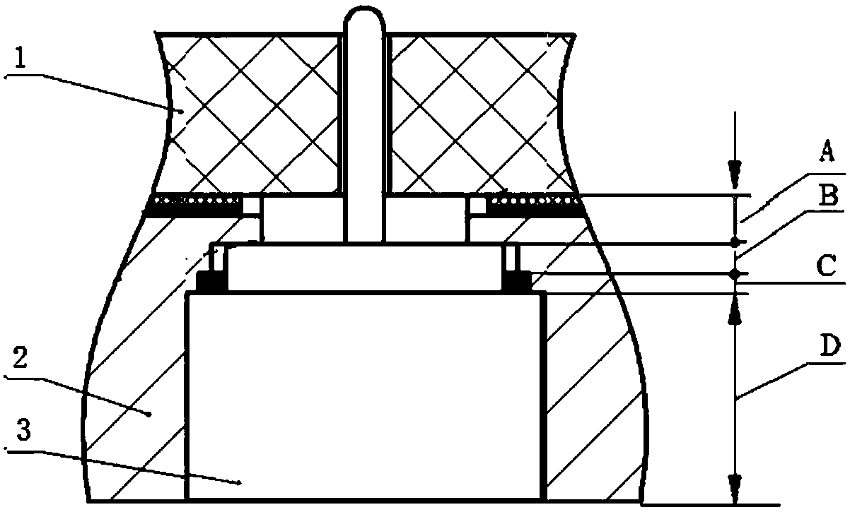
[0003] like figure 1 As shown, in order to ensure the reliable fixing of the structural component 2, the coaxial connector 3 and the substrate 1, ensure the ground continuity between the substrate 1 and the structural component 2, and realize the airtight packaging of the microwave module, solder paste is usually used for the The structural part 2 is welded with the substrate 1 and the coaxial connector, but in this process, on the one hand, due to the solder paste coating amount and coating on the welding surface between the substrate 1 and the structural part 2 and the coaxial connector 3 and the structural part 2 It is difficult to accurately control the coating area and coating uniformity, which leads to the fact that the solder paste is often squeezed into the air section A from the connection between the substrate 1 and the structural part 2 or the non-positioning section B in the extrusion state; on the other hand, in high temperature soldering During the process, the solder paste between the substrate 1 and the structural part 2 and the coaxial connector 3 and the structural part 2 is in a molten state, and its flow direction is difficult to control, resulting in the melted solder paste often flowing along the surface of the solder layer to the air section A
When solder paste enters the air section A, it will affect the shape of the impedance matching structure, making the standing wave performance of the port decrease, making it difficult to achieve the design performance

Method used


Image

  • A method of guaranteeing port standing wave performance
  • A method of guaranteeing port standing wave performance

Examples


Embodiment Construction

[0021] In order to make the objectives, technical solutions and advantages of the present invention clearer, the technical solutions in the embodiments of the present invention will be described in more detail below in conjunction with the drawings in the embodiments of the present invention. In the drawings, the same or similar reference numerals denote the same or similar elements or elements having the same or similar functions throughout. The described embodiments are some, but not all, embodiments of the invention. The embodiments described below by referring to the figures are exemplary and are intended to explain the present invention and should not be construed as limiting the present invention. Based on the embodiments of the present invention, all other embodiments obtained by persons of ordinary skill in the art without creative efforts fall within the protection scope of the present invention. Embodiments of the present invention will be described in detail below ...


PUM

PropertyMeasurementUnit
thicknessaaaaaaaaaa

Abstract

The invention belongs to the microwave technical field, in particular to a method for guaranteeing port standing wave performance. The method comprises the following steps: 1, enlarging the diameter of a non-positioning section and ensuring that the diameter of the non-positioning section is smaller than the diameter of a tin storage section; 2, arranging a solder sheet between a substrate and a structural member, wherein a solder hole is arranged in the solder sheet to expose an air section; 3, heating the solder sheet to melt to realize the weld of the substrate and the structural member; 4,coating the inner surfaces of the positioning section and the tin storage section of the structural member with a solder layer; 5, placing a coaxial connector in the structural dmember, heating the solder layer to melt, and realizing welding of the coaxial connector and the structural member. By optimizing the design of structural member and welding process, the port standing wave performance canbe effectively guaranteed.

Description

technical field [0001] The invention belongs to the field of microwave technology, and in particular relates to a method for ensuring the standing wave performance of a port. Background technique [0002] Most of the external microwave signal input and output ports of the microwave module are coaxial connectors, while the internal microwave signal input and output ports of the microwave module are mostly microstrip line structures set on the substrate, and the metal probes of the coaxial connector are transitionally connected to the microstrip line When , there is a certain discontinuity, which will affect the port standing wave. In order to eliminate the influence of the discontinuity of the transition connection on the standing wave of the port, the impedance matching design of the port is required. One of the commonly used methods for impedance matching design is to design air sections of different lengths and diameters on the structural parts according to the signals of ...

Claims


Application Information

Patent Timeline
Patent Type & Authority Applications(China)
IPC IPC(8): H01P11/00H01R43/02
CPCH01P11/00H01R43/0256
Inventor 代海洋何李婷贾双
Owner LEIHUA ELECTRONICS TECH RES INST AVIATION IND OF CHINA
Learn More