A fully automatic stamping system

A fully automatic, stamping machine technology, applied in the field of machinery, can solve the problems of no automatic feeding mechanism, no feeding mechanism, high personnel consumption cost, etc.

Active Publication Date: 2020-07-14
XIANGYANG TRADETOOL AUTOMOBILE PARTS
View PDF10 Cites 0 Cited by
  • Summary
  • Abstract
  • Description
  • Claims
  • Application Information

AI Technical Summary

Problems solved by technology

[0003] The purpose of the present invention is to provide a fully automatic stamping system to solve the problem that the traditional stamping work proposed in the above background technology is manual loading, and the risk factor is high, the cost of personnel consumption is too high, there is no good unloading mechanism, and there is no automation. The lower feeding conveying mechanism, the problem of lower feeding accuracy

Method used


Image

  • A fully automatic stamping system
  • A fully automatic stamping system
  • A fully automatic stamping system

Examples


Embodiment 1

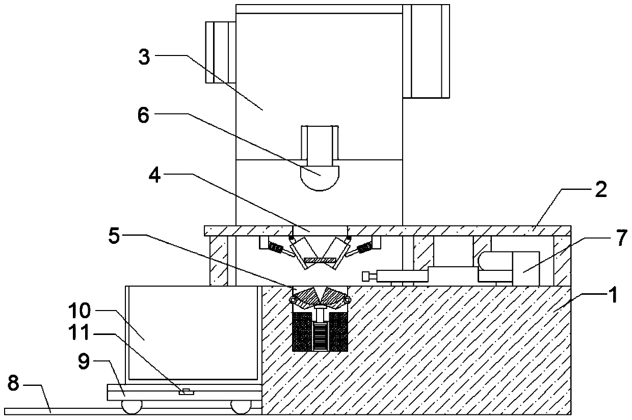
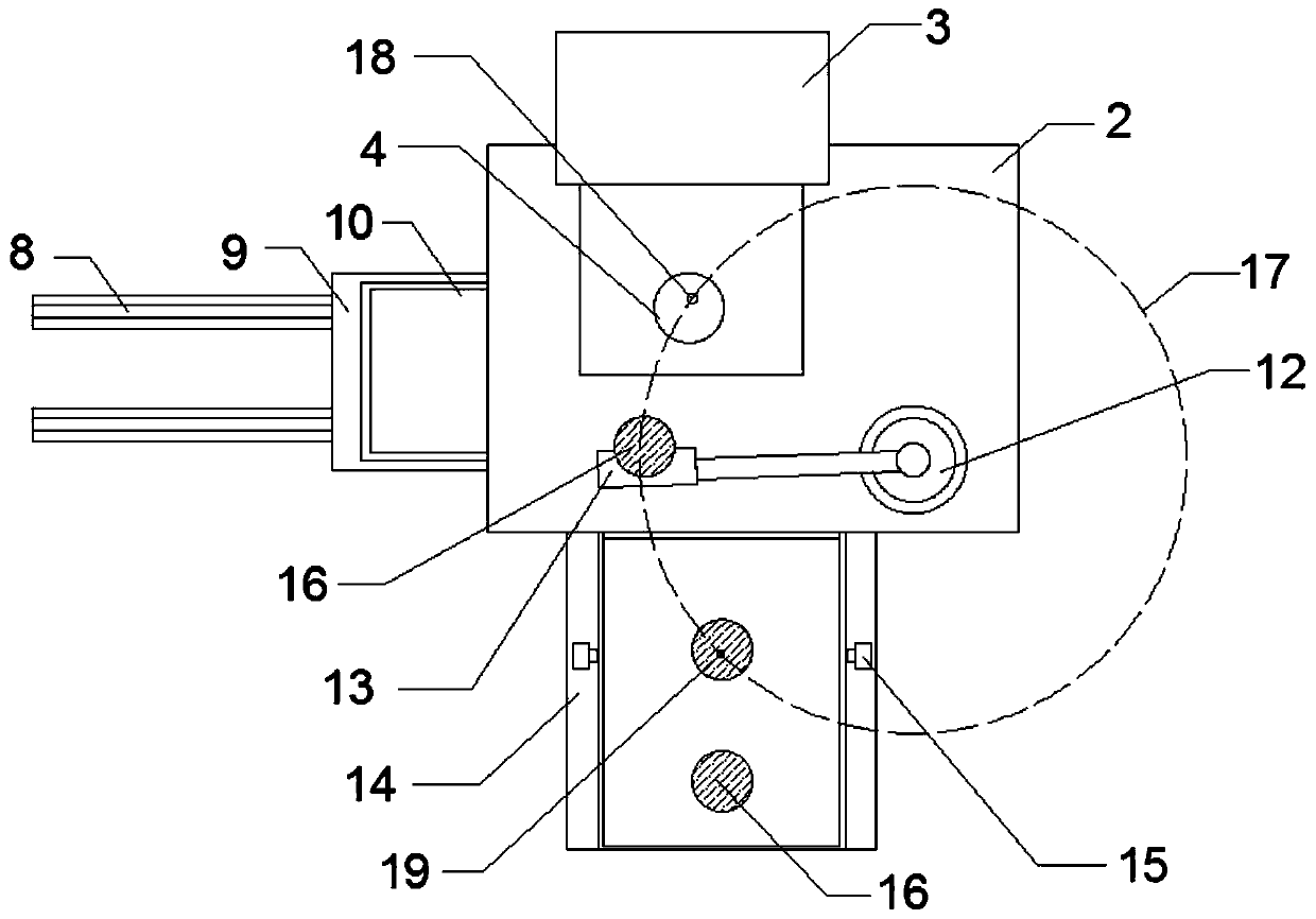
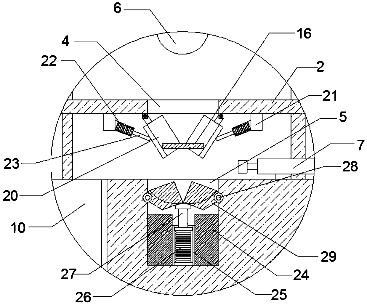
[0021] Such as Figure 1-3 As shown, a fully automatic stamping system includes a load-bearing base 1, a delivery plate 2, a punching machine 3, a delivery slot 4 and a die slot 5, the top of the load-bearing base 1 is installed with a delivery plate 2 through a mounting frame, and the delivery plate 2 One side is provided with a punching machine 3 through a connecting frame, one side of the top of the punching machine 3 has a punching top die 6, and the other side of the delivery plate 2 is provided with a corresponding conveyor 14, and the two sides of the top of the conveyor 14 are installed by bolts. Switch 15, and the steel plate 16 is placed by the transmission belt between the infrared switches 15, the speed reduction motor 12 is installed on the top side of the delivery plate 2 through the mounting seat, and the movement plate 13 is installed on the side of the reduction motor 12 through the connecting rod. 2. A drop slot 4 corresponding to the steel plate 16 is provid...

Embodiment 2

[0029] Such as Figure 1-3As shown, a fully automatic stamping system includes a load-bearing base 1, a delivery plate 2, a punching machine 3, a delivery slot 4 and a die slot 5, the top of the load-bearing base 1 is installed with a delivery plate 2 through a mounting frame, and the delivery plate 2 One side is provided with a punching machine 3 through a connecting frame, one side of the top of the punching machine 3 has a punching top die 6, and the other side of the delivery plate 2 is provided with a corresponding conveyor 14, and the two sides of the top of the conveyor 14 are installed by bolts. Switch 15, and the steel plate 16 is placed by the transmission belt between the infrared switches 15, the speed reduction motor 12 is installed on the top side of the delivery plate 2 through the mounting seat, and the movement plate 13 is installed on the side of the reduction motor 12 through the connecting rod. 2. A drop slot 4 corresponding to the steel plate 16 is provide...


PUM


Abstract

The invention discloses a full-automatic stamping system. The full-automatic stamping system comprises a bearing base, a putting plate, a stamping machine, a putting groove and a mold pressing groove,wherein the top of the bearing base is provided with the putting plate through a mounting frame, and one side of the putting plate is provided with a stamping machine through a connecting frame; oneside of the top of the stamping machine is provided with a stamping top mold, the other side of the putting plate is provided with a corresponding conveying machine, infrared switches are installed onthe two sides of the top of the conveying machine through bolts, and a steel plate is placed between the infrared switches through a conveying belt; one side of the top of the putting plate is provided with a speed reducing motor through a mounting base, and one side of the speed reducing motor is provided with a moving plate through a connecting rod; and a putting groove corresponding to the steel plate is formed in the surface of the putting plate, and a putting rail is formed among the putting groove, the conveying machine and the moving plate; and a point A is arranged between the conveying machine and the putting rail, a point B is formed between the putting groove and the putting rail, the speed reducing motor is a circle center of the putting rail, and the problem that an existinglabor cost is high is effectively solved.

Description

technical field [0001] The invention belongs to the technical field of machinery, and in particular relates to a fully automatic stamping system. Background technique [0002] The traditional stamping work is manual loading, and the risk factor is high, the cost of personnel consumption is too high, there is no good unloading mechanism, there is no automatic unloading and conveying mechanism, and the feeding accuracy is low, which does not meet the current market demand. Contents of the invention [0003] The purpose of the present invention is to provide a fully automatic stamping system to solve the problem that the traditional stamping work proposed in the above background technology is manual loading, and the risk factor is high, the cost of personnel consumption is too high, there is no good unloading mechanism, and there is no automation. The lower feeding conveying mechanism has the problem of lower feeding accuracy. [0004] In order to achieve the above object, t...

Claims


Application Information

Patent Timeline
Patent Type & Authority Patents(China)
IPC IPC(8): B21D22/02B21D43/14
CPCB21D22/02B21D43/14
Inventor 刘小军
Owner XIANGYANG TRADETOOL AUTOMOBILE PARTS
Why Eureka
Try Eureka