
Igniter miniature ring part multi-stage grabbing mechanism

A technology of ring-shaped parts and grasping mechanism, applied in metal processing, metal processing equipment, manufacturing tools, etc., can solve the problems of inability to automatically adjust, small picking range, etc., to reduce the type and quantity of equipment, reduce the complexity of the device, ensure The effect of device reliability

Active Publication Date: 2018-12-28
CHUANNAN MACHINERY PLANT CHINA ASTRONAUTIC SCI &TECH GROUP CORP
View PDF7 Cites 4 Cited by
  • Summary
  • Abstract
  • Description
  • Claims
  • Application Information

AI Technical Summary

Problems solved by technology

[0004] The technical problem solved by the invention is: to realize the picking of miniature ring parts in the automatic assembly process of the igniter, which has the characteristics of adjustable size classification and wide adaptability, and solves the problems of small picking range and inability to automatically adjust in the current technology

Method used

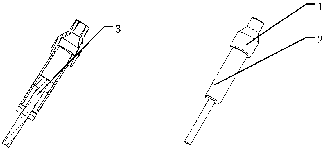
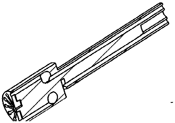
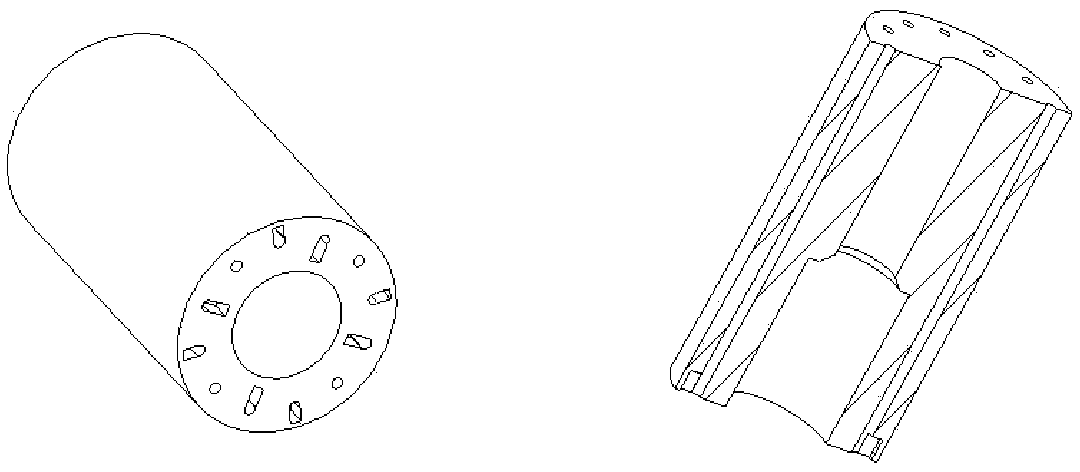

Image

  • Igniter miniature ring part multi-stage grabbing mechanism
  • Igniter miniature ring part multi-stage grabbing mechanism
  • Igniter miniature ring part multi-stage grabbing mechanism

Examples


Embodiment Construction

[0030] The invention forms a pneumatic piston structure through the internal air channels of the suction cups at all levels, and the suction cups at all levels can realize expansion and contraction to form a combination of suction cups with different diameters, so that a single head can pick up ring parts of various sizes.

[0031] The first-level suction cup 6 is fixed on the central position of the mounting plate 7; the inner hole of the second-level suction cup (5) is matched with the outer circle of the first-level suction cup (6) to form a shaft hole, and the inner hole of each level of the second-level suction cup is outwardly aligned with the mounting plate. The grading plate 10 on the mounting plate 7 cooperates, and the housing 1 is set on the outermost side; each level of suction cup except the first-level suction cup 6 is axially limited by the steps provided on the outer circular surface in contact with it; the mounting plate The nozzle on 7 communicates with the ai...


PUM

PropertyMeasurementUnit
Diameteraaaaaaaaaa
Diameteraaaaaaaaaa
Compressive strengthaaaaaaaaaa

Abstract

The invention relates to an igniter miniature ring part multi-stage grabbing mechanism. The miniature ring part multi-stage grabbing mechanism comprises at least two-stage suction cups and a grading plate. The first-stage suction cup is fixedly installed at the central position of a mounting plate. An inner hole of the second-stage suction cup forms shaft hole fit with the outer circle of the first-stage suction cup, the inner hole of each stage of suction cup outside the second-stage suction cup is matched with the grading plate mounted on the mounting plate, and a shell is installed on the outermost side in a sleeving mode. The suction cups except the first-stage suction cup perform axial limiting through steps arranged on the outer circular surfaces being in contact with the suction cups except the first-stage suction cup. Spray nozzles on the mounting plate communicate with air holes of the suction cups, and the adsorption is achieved by forming negative pressure on the outer end surface of each stage of suction cup. An air cylinder mounted on the mounting plate is used for pushing the suction cups except the first-stage suction cup to extend out, and the retraction of the suction cups is realized by introducing positive pressure into movable line cavities formed between the suction cups and adjacent structural members, so that the working adsorption area of the mechanism can be changed step by step. The igniter miniature ring part multi-stage grabbing mechanism realizes the completion of picking up ring parts of various sizes by a same machine head, the equipment flexibility is high, single control energy source is achieved, compatibility is good, the size and quantity of part picking devices in automatic equipment development can be effectively reduced, and the equipment development cost is reduced.

Description

technical field [0001] The invention is used to realize the pick-up and assembly of the mini ring part of the igniter, and belongs to the field of pyrotechnics assembly. Background technique [0002] The second-generation pyrotechnic igniter uses glass seals or tapered plugs as carriers, metal diaphragms as heating elements, and metal shells to restrict the output direction of ignition energy to achieve detonation and ignition. It has the advantages of insensitivity to electromagnetic signals, stable detonation, etc., and is widely used in strategic and tactical missile weapon systems, launch vehicles, satellites, fighter jets and other fields. The starting and firing components of control, booster separation, star-rocket separation and other devices. [0003] For a long time, due to the characteristics of multiple varieties, small batches, and high assembly precision, pyrotechnic igniters are mainly assembled by hand. In order to meet the needs of automation to improve pr...

Claims


Application Information

Patent Timeline
IPC IPC(8): B23Q7/00B23P19/00
CPCB23P19/00B23Q7/00
Inventor 徐嘉梁李毅罗云跃庄小威杨尹渝
Owner CHUANNAN MACHINERY PLANT CHINA ASTRONAUTIC SCI &TECH GROUP CORP
Learn More