Thickness planer for forming solid wood lines

A line and planer technology, applied in the direction of the planer, etc., can solve the problems of inability to adjust the user's height and low comfort, and achieve the effect of improving user comfort, improving stability, and avoiding self-rotation

Inactive Publication Date: 2018-12-28
柳州市品尚木业有限公司
View PDF8 Cites 4 Cited by
  • Summary
  • Abstract
  • Description
  • Claims
  • Application Information

AI Technical Summary

Problems solved by technology

[0004] The purpose of the present invention is to solve the problem that the height cannot be adjusted according to th...

Method used


Image

  • Thickness planer for forming solid wood lines
  • Thickness planer for forming solid wood lines

Examples


Embodiment Construction

[0019] The following will clearly and completely describe the technical solutions in the embodiments of the present invention with reference to the accompanying drawings in the embodiments of the present invention. Obviously, the described embodiments are only some, not all, embodiments of the present invention.

[0020] In describing the present invention, it should be understood that the terms "upper", "lower", "front", "rear", "left", "right", "top", "bottom", "inner", " The orientation or positional relationship indicated by "outside", etc. is based on the orientation or positional relationship shown in the drawings, and is only for the convenience of describing the present invention and simplifying the description, rather than indicating or implying that the referred device or element must have a specific orientation, so as to Specific orientation configurations and operations, therefore, are not to be construed as limitations on the invention.

[0021] refer to Figure ...


PUM


Abstract

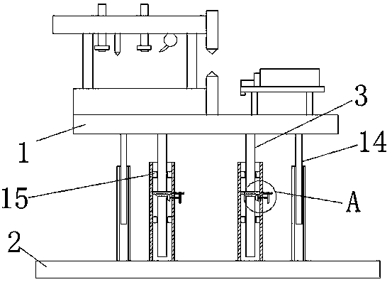
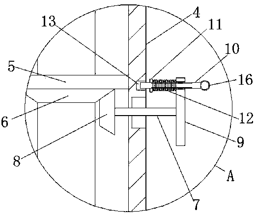
The invention discloses a thickness planer for forming solid wood lines. The thickness planer comprises a worktable, a clamping unit and a working unit, wherein the lower surface of the worktable is fixedly connected with a bottom plate through two lifting devices; each lifting device comprises a threaded rod fixedly connected with the lower surface of the worktable, the rod wall of the threaded rod is movably sleeved with a sleeve, the lower end of the sleeve is fixedly connected with the upper surface of the bottom plate, the inner wall of the sleeve is rotationally connected with a threadedbarrel which is in threaded connection with the threaded rod, the lower end of the threaded barrel is fixedly connected with a driven bevel gear which is movably arranged on the rod wall of the threaded rod in a sleeving manner, a through hole is formed in the outer wall of the sleeve, and a rotating rod is rotationally connected in the through hole through a bearing. Height of the thickness planer can be adjusted according to the height of a user, use comfort is improved, automatic rotation of the rotating rod can be avoided, and stability of the lifting devices is improved.

Description

technical field [0001] The invention relates to the technical field of solid wood production, in particular to a molding solid wood strip planer. Background technique [0002] The production process of solid wood moldings requires the use of planers for processing to obtain the required shape and size. [0003] After searching, the Chinese patent authorization number is CN206812127U, which discloses a new type of planer, including a machine body, which is provided with a clamping unit and a working unit, which are located at both ends of the top of the machine body; the clamping unit includes a first lift device, the first lifting device is fixedly connected with a slide rail, and a fixture is slidably connected to the slide rail. A limit ejector rod is provided at the end of the fixture near the working unit, and a motor is provided at the other end; the working unit includes a loading plate, a blanking plate and Second lift. The new planer in the above patent has the fol...

Claims


Application Information

Patent Timeline
IPC IPC(8): B27C1/04
CPCB27C1/04
Inventor 黄少北覃正贤
Owner 柳州市品尚木业有限公司
Why Eureka
Try Eureka