

Thermal insulation mechanism of deviated wall thickness adjusting device for glass tube production
A glass tube and partial wall technology, which is applied in the field of devices for adjusting partial wall thickness in the production of glass tubes, can solve the problems of reducing the efficiency of adjusting partial wall thickness in the production of glass tubes, the decline in cooling and heat insulation capabilities, and the inability to effectively isolate the lower temperature. , to achieve the effects of buffer protection cooling water bag, long service life and strong sealing
Inactive Publication Date: 2018-12-28
赵铮
View PDF1 Cites 0 Cited by
- Summary
- Abstract
- Description
- Claims
- Application Information
AI Technical Summary
Problems solved by technology
1. After the cooling water bag is installed in the heat insulation mechanism of the device, the cooling water bag is set in the insulating water tank. The disadvantage of the cooling water bag is that it can only absorb a certain amount of heat in a certain period of time, and then reach saturation. Its cooling and heat insulation The ability of the device will be relatively reduced, and the lower temperature cannot be effectively isolated to protect the device;
2. After the cooling water bag absorbs a certain amount of heat, it often takes a certain period of time to cool down before continuing to cool and insulate. It takes a long time to wait, which reduces the efficiency of adjusting the partial wall thickness of the glass tube produced.
Method used
View moreImage
Smart ImageViewing Examples

Examples
Embodiment Construction
Login to View More PUM
 Abstract
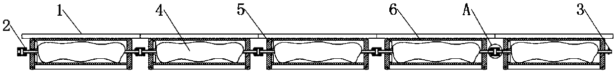
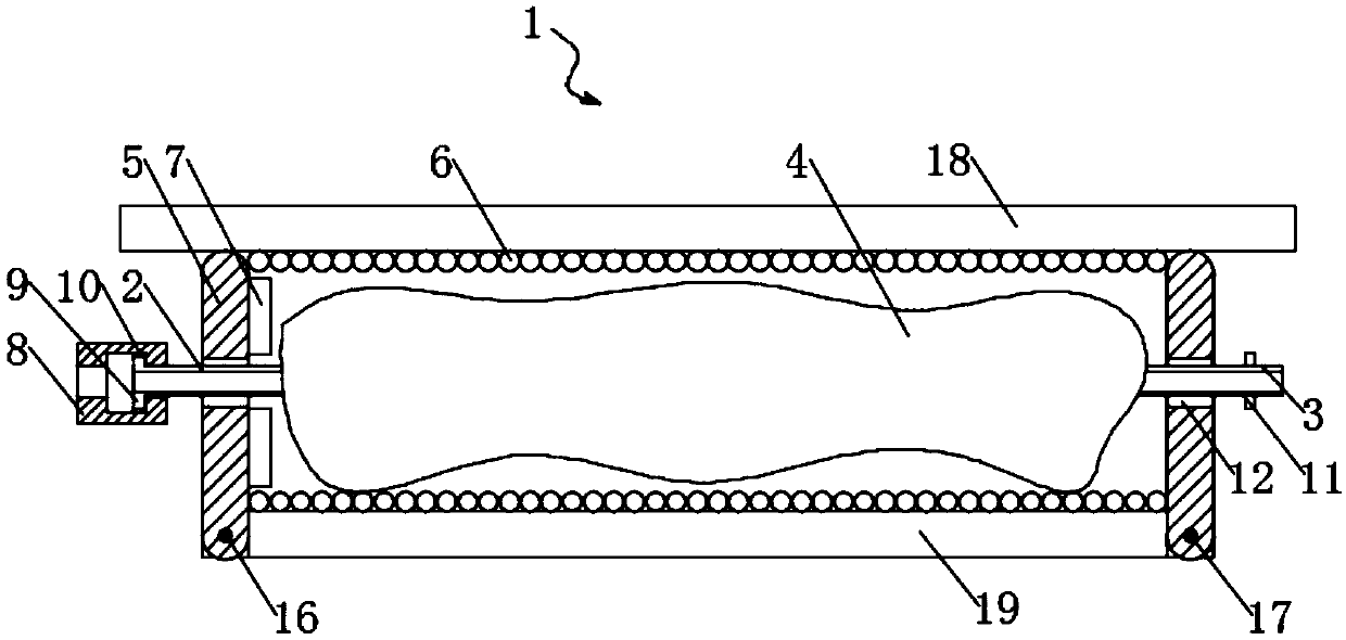
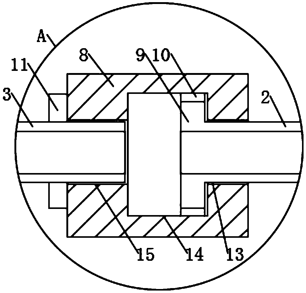
The invention discloses a thermal insulation mechanism of a deviated wall thickness adjusting device for glass tube production. The thermal insulation mechanism comprises a plurality of thermal insulation water tanks constituting the thermal insulation mechanism, wherein the thermal insulation water tanks are attached to one another from left to right, water coolers are arranged in the thermal insulation water tanks, and cushioning air pads are fixedly attached to inner walls of upper and lower ends of each thermal insulation water tank. The thermal insulation mechanism is formed by the plurality of thermal insulation water tanks, the water coolers in the thermal insulation water tanks are connected through a left-end water inlet pipe and a right-end water outlet pipe, so that water between the multiple water coolers circulates, and cooling and thermal insulation are relatively uniform; a circulating water pump is added to the left-end water inlet pipe at the end part, the other end ofthe circulating water pump is connected with the right-end water outlet pipe at the end part, accordingly, the water in the multiple water coolers can circulate and is subjected to cold-heat exchangewhen flowing to the outside, cooled water enters the water coolers again for use, efficiency is higher, lower heat can be insulated effectively, and the device is protected.
Description
technical field The invention relates to the technical field of devices for producing glass tubes for adjusting partial wall thickness, in particular to a heat insulation mechanism for producing glass tubes for adjusting partial wall thickness. Background technique The patent application number is: 201721300019.3, and the patent name is: A heat insulation mechanism for the production of glass tubes for adjusting partial wall thickness. In the literature, the heat insulation mechanism is equipped with a number of heat insulation water tanks, and the inside of the heat insulation water tank is equipped with cooling water bags. The device can adjust the size of the gap in the range of 360 degrees to ensure that the partial wall thickness of the glass tube is within the specified range, and the adjustment is more flexible, but it still has the following disadvantages in the actual use process: 1. After the cooling water bag is installed in the heat insulation mechanism of the d...
Claims
Login to View More Application Information
Patent Timeline
 IPC IPC(8): C03B15/14C03B17/04C03B23/045
CPCC03B15/14C03B17/04C03B23/045
Inventor赵铮
Owner赵铮