A discrete physical device for dismantling the structural bottom plate of a power battery module
What is Al technical title?
Al technical title is built by PatSnap Al team. It summarizes the technical point description of the patent document.
A power battery and module structure technology, which is applied in the mechanical field, can solve the problems of wasting physical strength and time for workers, and achieve the effect of avoiding manual disassembly of the power battery module bottom plate
Active Publication Date: 2019-10-11
江苏海涛新能源科技有限公司
View PDF4 Cites 0 Cited by
Summary
Abstract
Description
Claims
Application Information
AI Technical Summary
This helps you quickly interpret patents by identifying the three key elements:
Problems solved by technology
Method used
Benefits of technology
Problems solved by technology
[0003] When disassembling the power battery module, most of the bottom plates of the power battery module are placed manually, which is a waste of time; and when disassembling the power battery module bottom plate, some small processing plants often use manual power Remove the screws fixing the bottom plate in batches and remove the bottom plate of the power battery module from the bottom of the power battery module, which is a waste of physical strength for workers
Method used
Image
Click on the blue label to locate the original text in one second.
Reading with bidirectional positioning of images and text.
Examples
Embodiment Construction
[0026] The following will clearly and completely describe the technical solutions in the embodiments of the present invention with reference to the accompanying drawings in the embodiments of the present invention. Obviously, the described embodiments are only some, not all, embodiments of the present invention. Based on the embodiments of the present invention, all other embodiments obtained by persons of ordinary skill in the art without making creative efforts belong to the protection scope of the present invention.
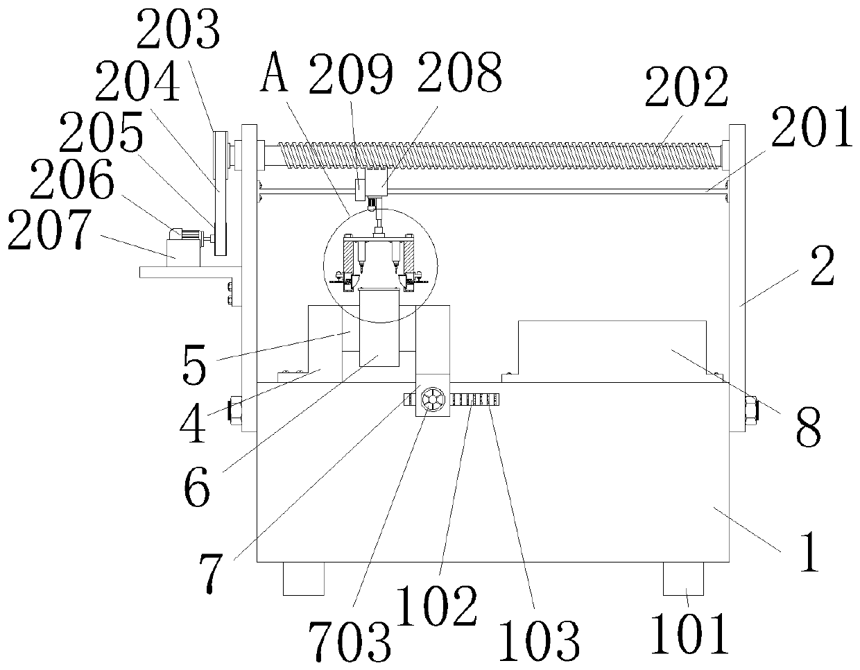
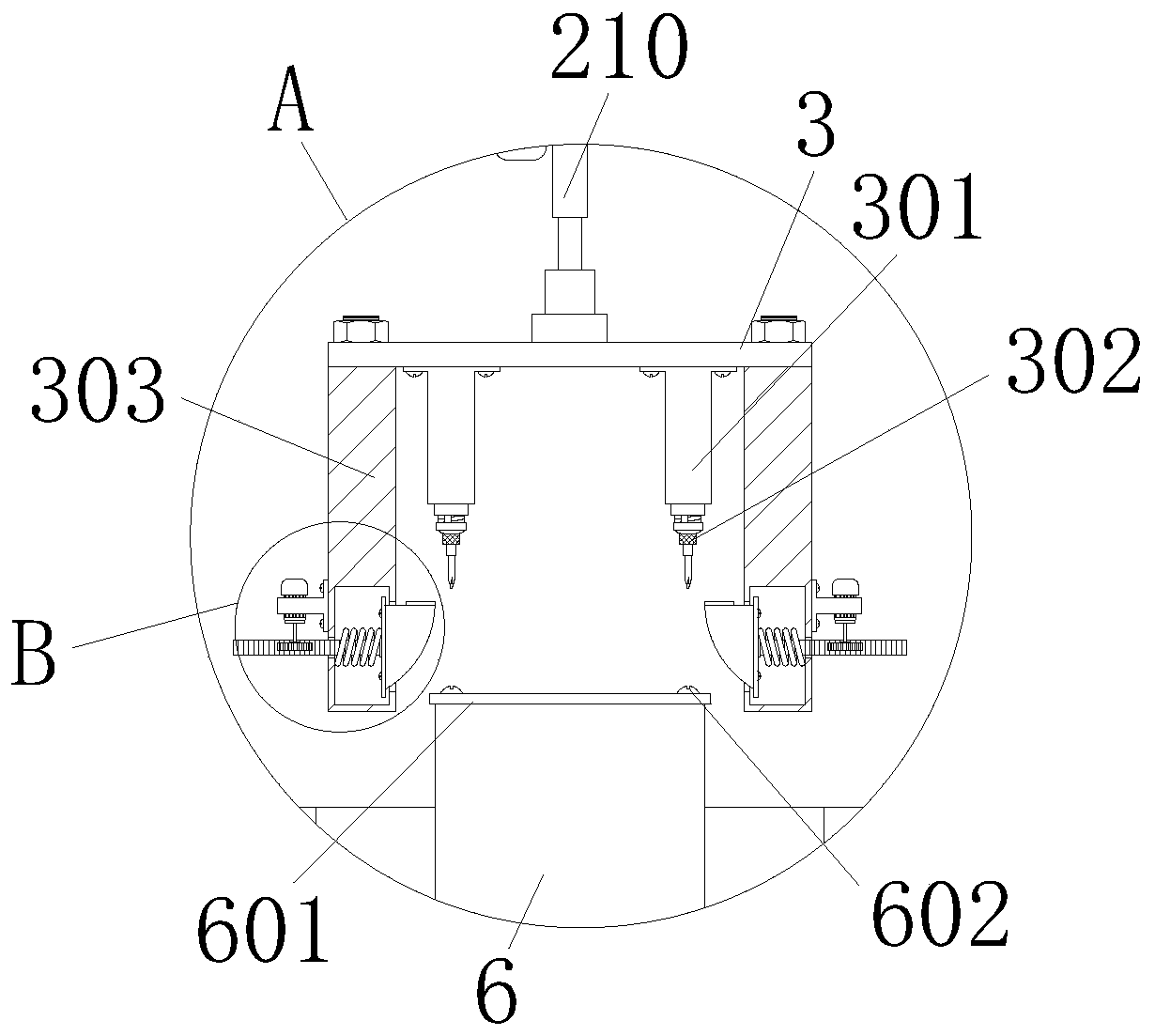
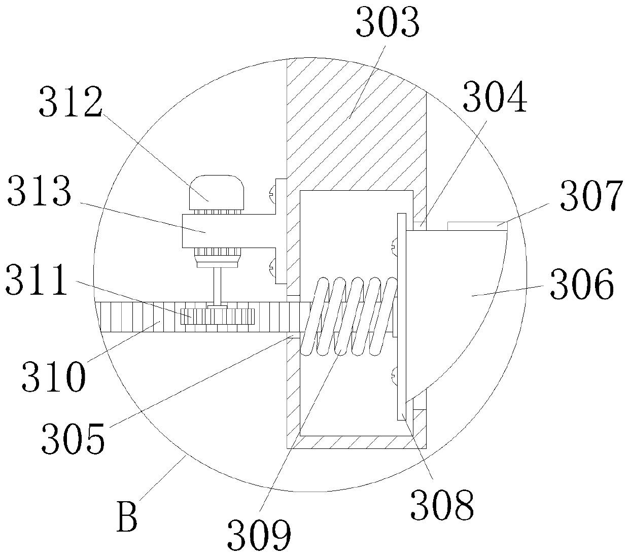
[0027] see Figure 1-5 As shown, a discrete physical device for dismantling the bottom plate of the power battery module structure includes a machine platform 1, a moving mechanism and a dismantling mechanism, wherein four identical tables are fixed symmetrically at the four corners of the bottom of the machine platform 1 The legs 101 are convenient for placing the device on the ground. The two opposite side walls of the machine table 1 are symmetrically provi...
PUM
Abstract
The invention relates to the technical field of machines, in particular to a discrete physical device for dismounting a power battery module structure bottom plate. The discrete physical device comprises a machine table, table legs, a sliding groove, anti-skid stripes, a supporting frame, a first square rod, a first threaded rod, a driven belt wheel, a transmission belt, a drive belt wheel, an electric machine, an electric machine support, a sliding block, a limiting block, an electric push rod, a supporting plate, a cylinder, an electric screwdriver, a second square rod, a first opening, a second opening, blocks, rubber gaskets, connecting sheets, springs, racks, gears, motors, motor supports, a first clamp, a rubber anti-skid block, a power battery module, the power battery module bottomplate, power battery module installing screws, a second clamp, a second threaded rod, a clamping block, a rotation handle, a material storage box, a partition plate and threaded holes. Through meshing connection of the first threaded rod and the sliding block and power provided by the electric machine, the detached power battery module bottom plate and the power battery module installing screws can be effectively placed in the material storage box.
Description
technical field [0001] The invention relates to the field of mechanical technology, in particular to a discrete physical device for dismantling the bottom plate of a power battery module structure. Background technique [0002] The power battery is the power source that provides the power source for the tool. It mostly refers to the battery that provides power for electric vehicles, electric trains, electric bicycles, and golf carts. When assembling the power battery, the power battery module also becomes an indispensable part. After the power battery that has reached its service life is scrapped, the power battery module can be removed and continued to be used. Recycling the power battery module not only reduces environmental pollution, but also reduces production costs. [0003] When disassembling the power battery module, most of the bottom plates of the power battery module are placed manually, which is a waste of time; and when disassembling the power battery module bot...
Claims
Application Information
Patent Timeline
Application Date:The date an application was filed.
Publication Date:The date a patent or application was officially published.
First Publication Date:The earliest publication date of a patent with the same application number.
Issue Date:Publication date of the patent grant document.
PCT Entry Date:The Entry date of PCT National Phase.
Estimated Expiry Date:The statutory expiry date of a patent right according to the Patent Law, and it is the longest term of protection that the patent right can achieve without the termination of the patent right due to other reasons(Term extension factor has been taken into account ).
Invalid Date:Actual expiry date is based on effective date or publication date of legal transaction data of invalid patent.