Multi-station sweeping equipment

A multi-station and equipment technology, applied in the field of machinery, can solve problems such as inability to realize speed, steering control, complex structure of transmission control, and affect processing effect, etc., and achieve good support effect, improved sweeping efficiency, and convenient operation.

Pending Publication Date: 2019-01-01
CSIC CHONGQING INTELLIGENT EQUIP ENG DESIGN
View PDF1 Cites 7 Cited by
  • Summary
  • Abstract
  • Description
  • Claims
  • Application Information

AI Technical Summary

Problems solved by technology

[0004] In the above-mentioned equipment, multiple turntables are uniformly driven by the same drive device, which cannot realize independent speed and steering control of each station, resulting in several turntables that can only move or stop at the same time. When it is necessary to stop or pick up a single workpiece , will lead to a unified emergency stop of multiple groups of turntables, which will inevitably reduce the processing efficiency and affect the processing effect; the upper turntable should completely cover the lower turntable, which has a large coverage area and is not compact in structure; When the workpiece moves from one station to the next, the upper and lower shafts need to be aligned and connected again, and the transmission control structure is complex

Method used


Image

  • Multi-station sweeping equipment
  • Multi-station sweeping equipment
  • Multi-station sweeping equipment

Examples


Embodiment 1

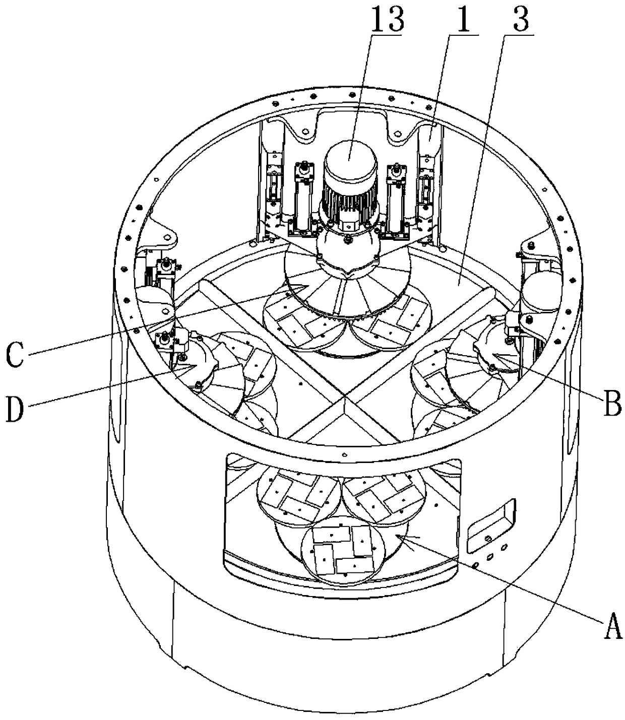
[0041] Such as figure 1 The multi-station sweeping equipment shown includes a bed 2 with a frame 1 on it and a plurality of positioning components for positioning workpieces, one of which is located at the loading and unloading station A, and the rest of the positioning components are located at the processing station at the workstation. Specifically, such as figure 1 The multi-station light-sweeping equipment shown has 4 stations, each station is equipped with a positioning component, and the 4 stations are distributed in a circular array, followed by the loading and unloading station A and the first processing station B. The second processing station C and the third processing station D. For example, the first processing station B is a rough grinding station, the second processing station C is a middle-magic station, and the third processing station D is a fine grinding station.

[0042] Such as figure 1 As shown, the frame 1 has a number of scanning components correspon...

Embodiment 2

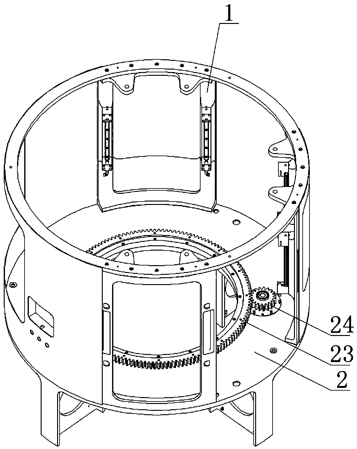
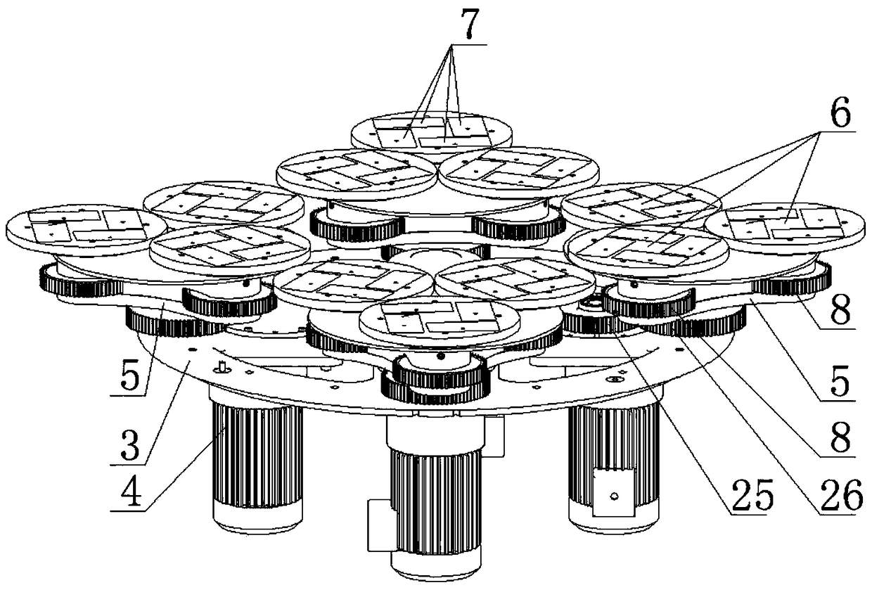
[0065] The structural principle of this embodiment is basically the same as that of Embodiment 1, the difference is that, as Figure 9 As shown, the output shaft of the motor is fixedly connected with a gear one 25 located above the rotating seat 3, and the power shaft 34 is coaxially fixed with a gear two 26 that is meshed with the gear one 25. When the output shaft of the motor rotates , drive the first gear 25 to rotate, and the first gear 25 drives the second gear 26 to drive the power shaft 34 to rotate.

[0066] Wherein, the power shaft 34 is sleeved with a planetary carrier 5, and the power shaft 34 is fixedly connected with an internal gear 36 above the planetary carrier 5, and the internal gear 36 meshes with the planetary gear 8 provided on the rotating shaft 35, and The outer ring of the planetary gear 8 is provided with a sun gear. When gear two 26 rotates, it drives the power shaft 34 to rotate, and the power shaft 34 drives the internal gear 36 to rotate, and th...

Embodiment 3

[0068] The structural principle of this embodiment is basically the same as that of Embodiment 1, the difference is that there are 3 stations in this embodiment: loading and unloading station A, first processing station B and second processing station C , wherein the first processing station B is a rough grinding station, and the second processing station C is a fine grinding station.


PUM


Abstract

The invention provides multi-station sweeping equipment, and belongs to the technical field of machinery. The multi-station sweeping equipment solves the problems that prior multi-station sweeping equipment cannot realize independent rotation speed and steering control of each station and has low working efficiency. The multi-station sweeping equipment comprises a bed body on which a frame is arranged. A rotating seat and a driving structure I for driving the rotating seat to rotate are arranged on the bed body. A sweeping assembly is arranged on the frame. A positioning assembly arranged corresponding to the sweeping assembly and used for positioning a workpiece is arranged on the rotating seat. By means of the multi-station sweeping equipment, multi-station simultaneous processing of a plurality of groups of workpieces can be realized, independent rotation speed and steering control of each station can be achieved, and operators can assemble and disassemble pieces conveniently, so that the processing efficiency is greatly improved, and the labor intensity of workers is effectively reduced.

Description

technical field [0001] The invention belongs to the technical field of machinery and relates to a multi-station optical sweeping device. Background technique [0002] Sweeping refers to the use of mechanical, chemical or electrical methods to reduce the surface roughness of the workpiece to obtain a bright and smooth surface. It is a processing method that uses sweeping tools and abrasive particles or other media to modify the surface of the workpiece. When the workpiece is placed on the workbench for processing, in order to ensure the uniformity of the sweeping of the workpiece, the workbench is generally set as a rotary workbench. The traditional sweeping device includes a single worktable that rotates around its central axis, which can only polish a single set of workpieces, and the working efficiency is limited. [0003] For this reason, the Chinese patent discloses a new type of precision sweeping machine equipment, method and application [application publication numbe...

Claims


Application Information

Patent Timeline
Patent Type & Authority Applications(China)
IPC IPC(8): B24B27/00B24B41/06B24B41/02B24B55/06B24B55/00B24B7/24
CPCB24B27/0023B24B7/242B24B27/0015B24B27/0069B24B27/0076B24B41/02B24B41/06B24B55/00B24B55/06
Inventor 刘祖涛吴小虎王亚林
Owner CSIC CHONGQING INTELLIGENT EQUIP ENG DESIGN
Why Eureka
Try Eureka