Supercharge Your Innovation With Domain-Expert AI Agents!

Ballastless rail retractor

A technology for rerailers and rails, which is applied to railway car body components, equipment fixed on the rails, transportation and packaging, etc., and can solve the problem of short distances, inability to install herringbone rerailers, and inability to use inner rerailers and other issues to achieve the effect of avoiding secondary derailment, high operational safety and convenient installation

Inactive Publication Date: 2019-01-01
佛山三水鼎力液压机械设备有限公司
View PDF8 Cites 0 Cited by
  • Summary
  • Abstract
  • Description
  • Claims
  • Application Information

AI Technical Summary

Problems solved by technology

There are two kinds of ballast beds in the existing high-speed railway, one is the ballastless track bed used in the main line and the section, which is characterized in that the height of the top surface of the rail is 250mm from the overall track bed, and the bottom surface of the rail is 70mm higher than the surface of the overall track bed, while the traditional ballasted track bed The bottom surface of the track bed rail is 20mm lower than the sleeper surface, and the difference between the two is 90mm, which makes the traditional herringbone rerailer unable to be installed and used
The other is the slab sleeper track bed used on the line in the station. The distance between the sleepers is 100-120mm, the width of the sleeper is 460m, and the length is 2500mm. It is laid as a ballastless line. The existing herringbone rerailer cannot be installed.
In addition, the patent and literature also disclose a multifunctional rerailer, publication number CN203381644U, publication date: 2014.01.08, the provided rerailer is light and can also be used in ordinary slag rails, but when in use, its Relying on the inner rerailer to guide the wheel rerailing, when the guide rib slot 22 is installed with the guide block, its length is longer, while the distance between the wheel of the EMU train and the axle box of the EMU train is short, the inner rerailer cannot Used in the rails of EMU trains

Method used


Image

  • Ballastless rail retractor
  • Ballastless rail retractor
  • Ballastless rail retractor

Examples


Embodiment Construction

[0017] Below in conjunction with accompanying drawing and specific embodiment, the present invention will be further described:

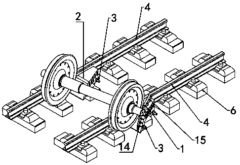
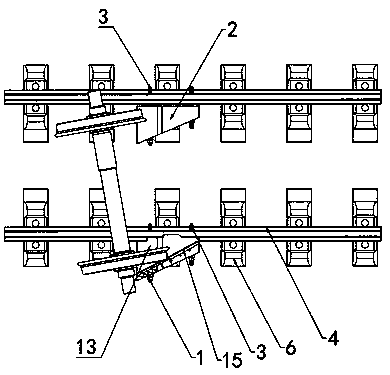
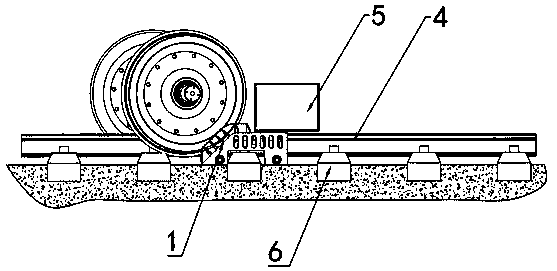
[0018] refer to Figure 1 to Figure 6 , a ballastless rail rerailer, comprising an outer rerailer 1 and an inner rerailer 2, the lower part of the outer rerailer 1 has a first positioning groove 11 matched with a sleeper 6, and the outer rerailer 1 has a first through hole 12, the tension screw 3 passes through the first through hole 12 and the outer rerailer 1 is closely installed on the outside of the rail 4, there are two first through holes 12, and they are separated from the On both sides of the first positioning groove 11, the outer rerailer 1 has a first slope surface 13, the lower part of the first slope surface 13 is inclined and the upper part is horizontal, and there is a smooth transition between the slope surface and the horizontal surface. The top of the first slope surface 13 There is a fixed guide block 14 on the top, and a pluralit...


PUM


Abstract

The invention provides a ballastless rail retractor comprising an outer re-orbiting device and an inner re-orbiting device, the lower portion of the outer re-orbiting device has a first positioning groove, the outer re-orbiting device has a first through hole through which a tensioning screw passes, the outer re-orbiting device has a first slope surface, a fixed guide block is arranged on that topof the first slope surface, the lower portion of the inner re-orbiting device having a second positioning groove, a second through hole is provided for the inner re-orbiting device to be passed through by the tensioning screw, the inner re-orbiting device has a second slope surface, a movable guide block is movably inserted along the tail end of the fixed guide block, one end of the tensioning screw is a hook for clamping the rail side surface, the other end is threadedly connected with a nut, the top of the first slope surface is slightly higher than the rail, the top of the second slope surface is lower than the rail and ensures that the wheelset tread on the inner side of the rail can be mounted on the rail. The v can be used in the ballastless rail, and can re-orient the EMU train very well, is convenient to install, has high operation safety, and avoids secondary derailment.

Description

technical field [0001] The invention belongs to the technical field of train rerailing, in particular to a ballastless rail rerailing device. Background technique [0002] As the most important and economical mode of transportation in the world today, railway transportation has an irreplaceable advantage in the world freight and passenger transportation market. At present, the rerailers commonly used in China are herringbone rerailers and traverse rerailers. The herringbone type rerailer is used for hoisting the hook or axle of the vehicle. It is safer for the operator to operate outside the vehicle, and it is convenient and quick when there is power; It is unsafe to work under the ground, because it can only lift and reset the axle of the vehicle, the starting and returning point is single, and the adaptability is poor. With the opening of the Wuhan-Guangzhou high-speed railway, it symbolizes that my country's railways have entered a high-speed era, and the rescue and rec...

Claims


Application Information

Patent Timeline
Patent Type & Authority Applications(China)
IPC IPC(8): B61K5/06
CPCB61K5/06
Inventor 禤荫江吴海华任慧明梁永鉴王志聪陈永豪
Owner 佛山三水鼎力液压机械设备有限公司
Features
  • R&D
  • Intellectual Property
  • Life Sciences
  • Materials
  • Tech Scout
  • Unparalleled Data Quality
  • Higher Quality Content
  • 60% Fewer Hallucinations
Learn More